Pavement LCA - Tutorial
Overview
In this tutorial, we attempt to introduce you to a number of features of the Pavement LCA, focusing on those aspects of the software that you will use every time you start it up.
The tutorial has been broken into sections in order to make it easier to follow and to help make it a useful reference.
Here is a brief outline of what we will be covering:.
SECTION 1: INTRODUCTION
SECTION 2: GENERAL
- Set Application Options.
- Manage the Procuct Library
- Manage the Equpiment Libary.
SECTION 3: TUTORIAL PROJECT 1
- Create a Project - name it "Tutorial Project 1".
- Add a Roadways Assembly.
- Add Extra Basic Materials - Concrete.
- Save the Project.
- Generate Project Results.
SECTION 4: TUTORIAL PROJECT 2
- Duplicate the Project - rename it "Tutorial Project 2".
- Modify the Asphalt Roadway from "Tutorial Project 1".
- Change it to Concrete pavement and shorten it.
- Copy the Asphalt roadway from "Tutorial Project 1" into "Tutorial Project 2" and shorten it.
- Generate a Bill of Materials for " Tutorial Project 2".
SECTION 5: COMPARISON REPORTS
- Generate Comparison Reports.
SECTION 6: SAMPLE PROJECTS
- Open the Sample Case Study Project Files.
Introduction
Introduction to Using the Athena Pavement LCA
This self-guided tutorial describes how the application works from a user’s perspective, with illustrations of some of the screens, dialog boxes and tool bars as well as a discussion of some other application features. You can choose to either just read through the following passages or follow along by actually duplicating some of the example input screens presented – as we all learn more quickly by doing, we highly recommend the latter.
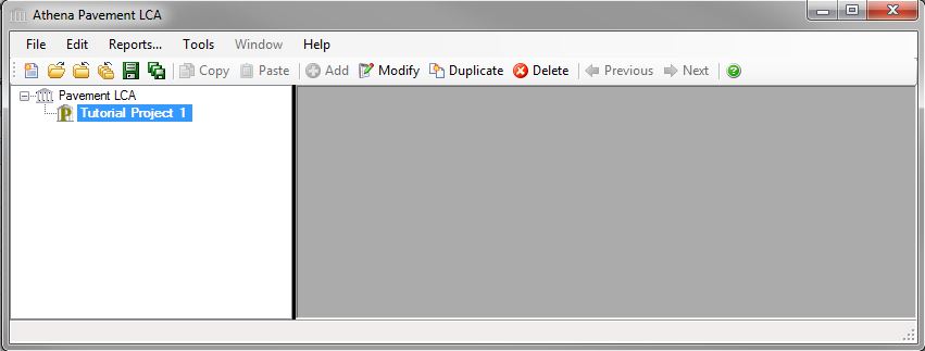
When you first open the Pavement LCA application, a familiar Application Program menu bar, the "Main Menu", appears immediately under the Athena Pavement LCA window title bar. The "Main Menu" consists of File, Edit, Reports, Tools, Window, Help submenus. Located under the "Main Menu" is a set of familiar icons in the "Toolbar". When the software is first started up, the toolbar can be used to initiate project assessments by either creating a new project input file or opening an existing (previously saved) project input file. See the "Pavement LCA Menus" help file for more information.
As with most application programs, you can use the File menu to either create a New project input file or Open a previously saved project input file. You can also click on the first icon (reading left-to-right) to create a new project input file or click on the second icon to open a previously saved project input file. By default, all saved project input files reside in the main Pavement LCA folder unless you select another directory/folder pathway when executing a "Save As" file operation. We recommend that you save project input files to a folder in your "My Documents" (Windows XP), "Documents" (Windows Vista or Windows 7) or similar folder that is not located within the "Program Files" folder.
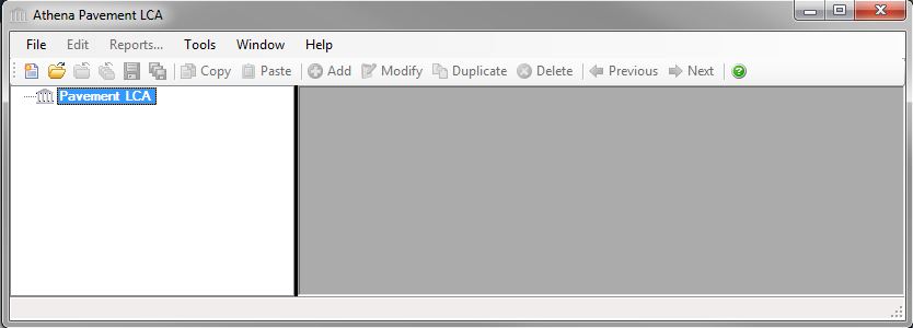
Immediately below the icon toolbar you will see the Pavement LCA Tree Control window which operates as a hierarchical viewer of all inputs into the application; allowing you to create and compare projects, insert assemblies, track (review) your design (assembly) inputs and edit (modify) them. Essentially the Pavement LCA Tree Control window allows you to perform the logic operations offered on the main menu bar. For example, within the Pavement LCA Tree Control window you will see the Pavement LCA’s Root Node highlighted (Pavement LCA). With your mouse pointer on the highlighted Root Node "right click" to activate a new vertical menu list (also referred to as the "right click menu"). From here you can create a New project, Open a previously saved project, Save all active projects, Close all active projects and a number of other operations. See the "Using the Pavement LCA Tree Control Window" help file for more information.
The following sections will describe the input and output operations using the Pavement LCA Tree Control window as the primary method for navigating through the application.
Please note that the software is packaged with a context sensitive HELP file, which provides detailed directions for inputting designs and interpreting results. Click here to access the main help file.
Options
Set General Software Options
Click the "Tools" main menu option to display the "Tools" submenu.
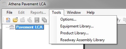
Click "Options" to open the "Options" dialog. The "General" tab of the "Options" dialog provides the user with the opportunity to set some application behaviour preferences. Selecting the "Options" menu item from the "Tools" menu opens the "General" tab of the "Options" dialog. See the "Options - General" help file for more details.
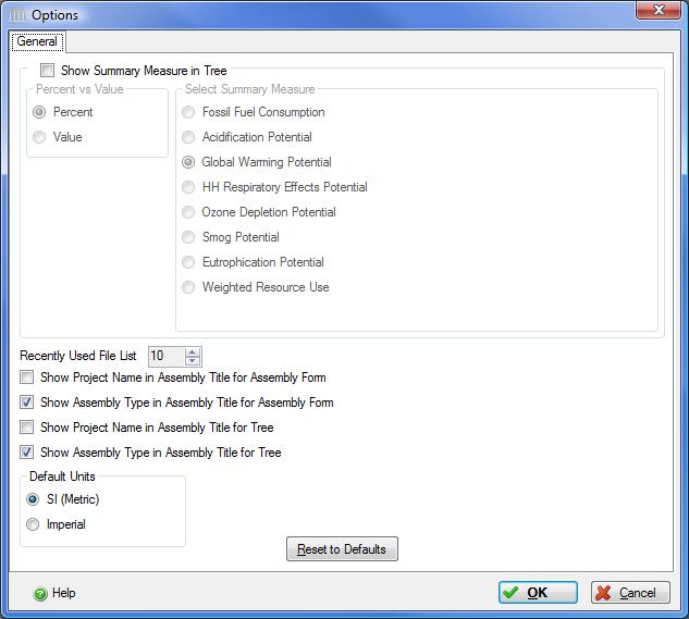
The Pavement LCA Tree Control Window may be configured to display one of the summary measures for a project as either a percent or actual value for the embodied effects.
To enable this feature, select "Show Summary Measure in Tree", the "Percent" radio button and the "Global Warming Potential" radio button.
Continue making changes to the "Options" form so that your "Options" are the same as those above. If you prefer to work in "Imperial" units, make sure that you select the "Imperial" Default Units radio button.
Manage the Product Libraries
There are many predefined "Products" in the Pavement LCA database. Products are made up of component materials. For example, Superpave 12.5 Asphalt is a product that is composed of 4 materials, Bitumen, Fine Aggregate, Mineral Filler and Coarse Aggregate, in specific percentages by weight.
To access the "Custom Material Component Product Library " form, Click the "Tools" main menu option to open the "Product Library" dialog.
See the " Open Composite Product Library " help file for more details.
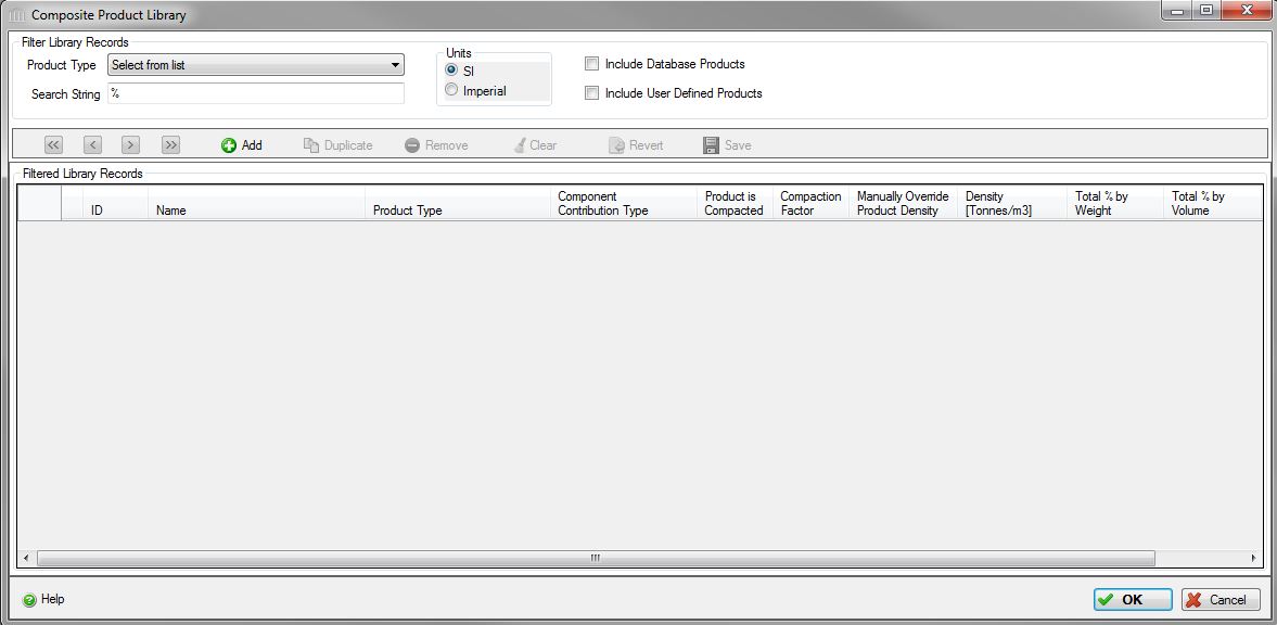
Follow these steps to create a new product:
- Click
the
"Add "
 to
create a new product.
to
create a new product. - The product will be named "New User Defined Composite Product#" where # is blank or an integer (1, 2, 3, ...). You can rename this by selecting the Name box in the Selected Product Info section, and typing "Tutorial Asphalt"
- Select the Product Type from the drop down list in the next column, in this case, Asphalt Pavement HMA .
- Check the "Product is Compacted" checbox.
- Clear the "Manually Override Product Density" checkbox.
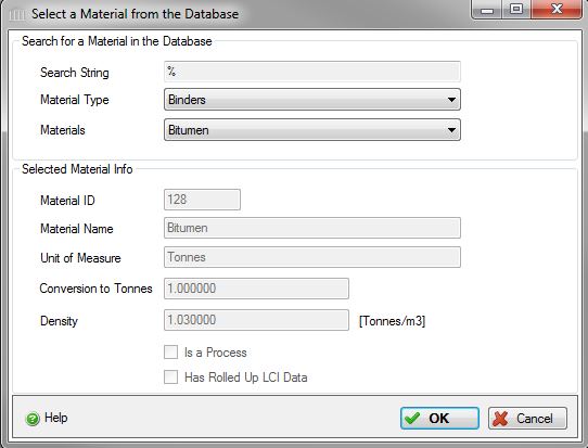
- Click the Add button to open the "Select a Material from the Database" form
- Select a Material Type - Binders - and a Material - Bitumen - from the drop down lists. Then click OK.
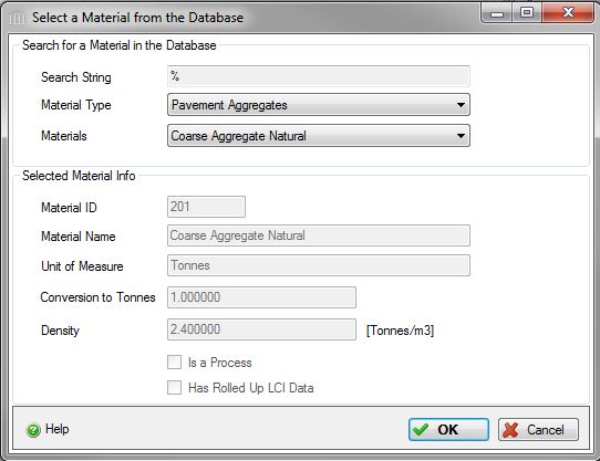
- Select a Material Type - Pavement Aggregates - and a Material - Coarse Aggregate Natural - from the drop down lists. Then click OK.
- Click the Cancel button to close the Select a Material from the Database dialog and return to the Composite Product Record dialog.
- In the Components box, assign a % by Weight of 5% to the bitumen and 95% to the aggregate. These percentages must add up to 100% before you can proceed.
- Click the "Calculate" button to calculate the product level Compacted Density.
- Click OK, and your new product will appear in the Composite Product Library. If you want to edit the new product, click on the edit icon in the leftmost column to re-open the Composite Product Record

-
You can also select an existing product from the database, duplicate it
to create a new product, and then add or remove materials, or adjust
existing percentages to create a new custom product.
Manage the Equipment Library
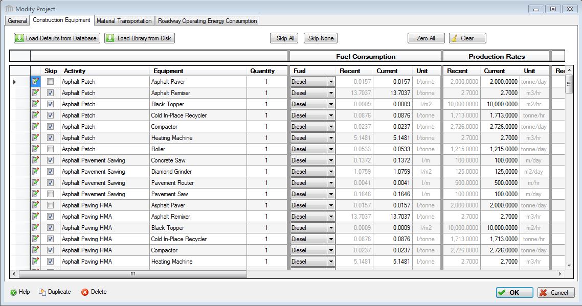
There is a library of construction equipment in the Pavement LCA database that are used to model the construction energy of each project. The equipment list is set in the database, and the the default fuel usage values are calculated from several factors, each of which is editable by the user to match the specific set of equipment or conditions of the project. See the " Open Equipment Library " help file for more details on how to customize your equipment table.
To access the "Custom Material Component Product Library " form, Click the "Tools" main menu option to open the "Equipment Library" dialog.
If the table is blank, Click "Load Defaults from Database", and it should appear as below.
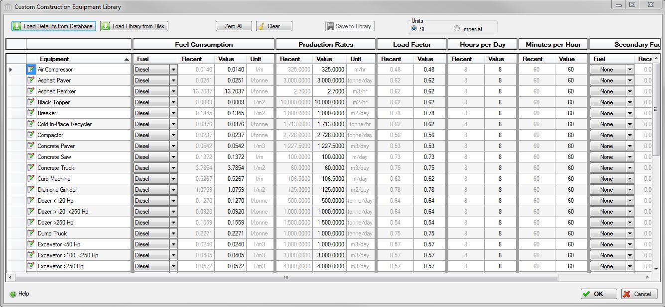
- Let's assume the fuel consumption data for the Asphalt Paver in the second row of the table does not match the actual piece of equipment that you're using on this project and you wish to change it.
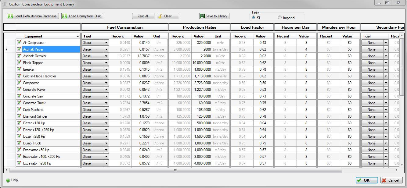
- The units are in litres per tonne of asphalt, and 0.0251 is too much, you can click on the Fuel Consumption User cell for the Asphalt Paver and change it to whatever value you think is appropriate.
- We're going to assume that you don't know the correct value for your paver, but you do know some of the other data in the table. Let's say you know that your paver can pave 2000 tonnes per day instead of 3000, that you use the paver constantly for 50 minutes for every hour, but only for four hours a day.
- Click on the User cells for Production Rates, Hours per Day and Minutes per Hour, and change those values to 2000, 4 and 60 respectively.
- Note that the Fuel Consumption User cell has changed value to 0.0157 and should look like the table below.
- Let's assume there is no Secondary Fuel Consumption for the paver (e.g. Propane for heating the material), and leave those columns blank.
- Click "Save to Library" to preserve the new values in your custom equipment library, to be used in any project.
- Click OK to close the table.
You can customize the data for any other piece of equipment in the table that you feel does not reflect the actual equipment that your are modelling.
TUTORIAL PROJECT 1
Create a New Project
Now that you've defined a custom project and customized your
equipment table, you can create a new project. Immediately below the
toolbar you will see the Pavement LCA Tree Control window, which
operates as a hierarchical viewer of all inputs into the model. Within
the Tree Control window you will see the Pavement LCA Root node
highlighted. With your mouse pointer on the
highlighted Root node, "right click" to activate a new vertical menu
list (also referred to as the right click menu). Click-on "New Project"
in the right click menu to open the "Add Project" dialog box.
Alternatively, you can click on the ![]() "New" button
on the far left side of the toolbar to open the "Add Project" dialog box
"New" button
on the far left side of the toolbar to open the "Add Project" dialog box
Here, you are asked to enter some general information about the project to be modeled. You can either navigate through the dialog box using your tab key or by simply using your mouse pointer to toggle various “radio buttons” or enter text, where appropriate. Note that you must enter a project name, project location, roadway project life – all other information, including annual operating energy values, is optional. When you are finished adding project information, click the “OK” button to save the changes and close the “Add Project” dialog. A new Project [P] level node with the title you gave the project will be added to the Tree Control immediately under the Root node. See the "Add or Modify a Project" help file for more details.
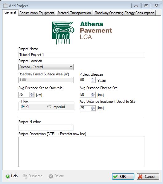
As in the image above, enter the following information:
- For the "Project Name", enter "Tutorial Project 1".
- Select "Ontario - Central" from the "Project Location" list.
- Enter 75 km for the "Avg. Distance Site to Stockpile ". This value is used to calculate transportation effects of materials that are removed from the site.
- Select 50 km from the "Avg. Distance Plant to Site". This value is used to calculate transportation effects of materials transported from the plant to the site (e.g., cement concrete, asphalt).
- Select 25 km from the "Avg. Distance Equipment Depot to Site". This value is used to calculate transportation effects of floating equipment to the site.
- Enter 50 years for the for the "Project Lifespan". This is used to enalbe the comparison of different projects on the same time basis.
- For the "Units", select
the "SI" radio button. This is the default Units that
you want the application to use when opening dialog boxes for data
input and reporting bill of material quantities. The SI (metric) unit
designation is the default for entering assembly information. While the
inputs to the application can be specified as either US Imperial or
(SI) metric, the internal application working units are metric and
final results are also presented in metric units.
The remainder of this tutorial assumes that you selected the Select the "SI" radio button.
Both the "Project Name" and "Project Location" are two pieces of information that must be entered because they activate a number of critical functions in the application.
Click on the Construction Equipment tab at the top of the dialog and click "Load Library from Disk" to use the custom equipment table that you defined in Manage Equipment Library previously. check that the Asphalt Paver Fuel Consumption value is the same as you changed it to above. If you wish you can specify any other equipment values for this project here. Any changes made here will only be available in this project (or any duplicates), not in any newly created projects.
Click on the Material Transportation tab at the top of the dialog and click "Load Defaults for Database" to populate the table. You need to determine from how far away and using what mode of transport that your materials are sourced and input those distances in this table. For this exercise, let's input 50 km of truck transportatiion for each material.
Enter Operating Energy Consumption
The "Roadway Operating Energy Consumption" tab on the "Add Project" form allows you to input annual roadway operating energy for the roadway by fuel type (this is another optional input). It is assumed that this operating energy information would come from another simulation tool. The application takes this energy information and converts it to primary energy and calculates related emissions to air, water and land. Later the user may then compare and contrast embodied and operating energy and emissions within and between up to 5 projects. If your operating energy output is in MJ or BTUs rather than physical units of fuel, simply click on the compute fuel button next to the fuel of interest to have the application convert the fuels energy value into physical units. The application then automatically calculates and enters this quantity of fuel in the Annual Operating Energy Consumption table. See the "Roadway Operating Energy Consumption" help file for more detailed instructions on using the compute fuel conversion.
Click on the "General" tab.
Click on the "Operating Energy Consumption" button.
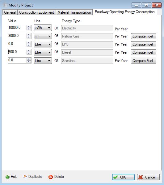
As in the image above, enter the following information:
- Enter 10,000 kWh of Electricity,
- Enter 8,000 m3 of Natural Gas, and
- Enter 300 Litres of Diesel.
Once the initial project descriptors have been selected, click on the "OK" button to save the information and exit the dialog box. Click the "Cancel" button to discard the new project. In the Pavement LCA Tree Control window you will now see a plus sign (+) in front of the Root Node. By clicking on the plus sign a Project [P] level object will appear with the title "Tutorial Project 1". You have now successfully created a new project.
Defining a Roadway
Now you are ready to start adding Roadway Elements (Assemblies) to the project. To define an assembly, right click on the Project [P] level node to activate the right click menu. At the bottom of the menu will be a listing of assemblies "Add Roadways" and "Add Extra Basic Materials". Select the assembly of interest to you.
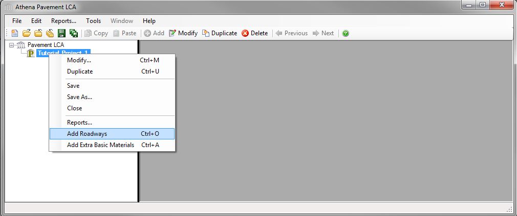
Select "Add Roadways" and a “Add Roadway” dialog will appear. The the “Name” box wiil be highlighted. Each assembly must first be given a name; otherwise no data input is possible. After entering a roadway name (e.g., Apshalt Highway ), tab to each of the data input boxes or, using your mouse, place the cursor in each to describe the roadway’s geometry and attributes as shown below in the Survey section. For more details see Add or Modify a Roadway Assembly.
After Entering the Survey data, click Apply and the Roadway Cross Section and Roadway Design Details will be generated.
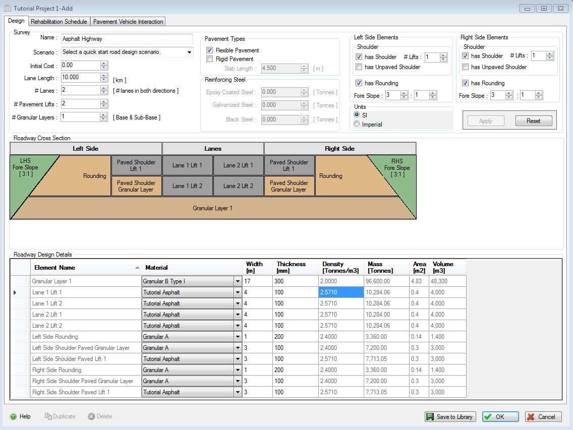
Now fill in the Roadway Design Details as above. For example, the Granular base layer is Granular B Type I, has a width of 17 metres and a thickness of 300 millimeters. The other granulars are Granular A, and note that you can choose the "Tutorial Asphalt" pavement product that you defined in Manage the Product Libraries earlier, for the lane and shoulder pavement lifts.
You can click "Save to Library" if you wish to save this design for use in other projects. After saving to library, check to make sure Asphalt Highway has been added to the library by clicking on the Scenario drop down list to make sure it's on the list.
When you're done, click OK to save the assembly.
If prompted with a "Pavement Vehicle Interaction validation error" message, click the "No" button to ignore, this will turn off the PVI Effects calculation module.
After entering the roadway details and clicking the "OK" button, the assembly dialog box will close and a new plus sign [+] will appear beside the Project [P] level object in the Tree Control Window.
If you click on the [+] sign you will cascade to the Assembly Group Node, clicking on the [+] sign beside the Assembly Group takes you to the a list of Assembly Nodes. Double clicking on an Assembly Node will open the "Modify Assembly" dialog.

Define a Maintenance and Rehabilitation Schedule
Now you can define the maintenance and rehabilitation schedule for the project. In the Tree Control Window, double click on the Assembly level node [A] "Asphalt Highway" to open the Modify Roadway dialog, and click on the Rehabilitation tab at the top.
Let's add one maintenance and one rehabilitation activity to the schedule. For more details on completing this form see Add or Modify a Roadway Maintenance and Rehabilitation Schedule .
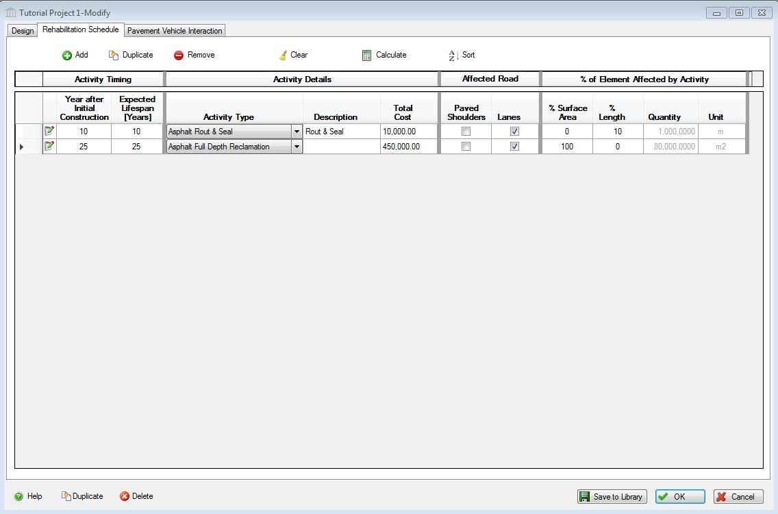
Let's add a rout and seal activity at 10 years after initial construction and a full depth reclamation after 25 years. This will actually be 6 activties, Crack Cutting, Crack Cleaning and Drying and Asphalt Sealant Material Installation, for the rout and seal, and Full Depth Reclamation, Tack Coat Application and Asphalt Paving for the reclamation.
Asphalt Rout & Seal
- Click Add to add a new row to the table. The "Modify Rehabilitation Schedule Activity Record" form will automatically launch.
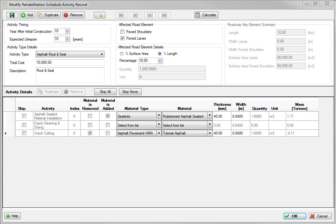
- Fill in the form as illustrated in the screen shot below (also described verbally below the screen shot).
- For Activity Timing, set it at 10 Years After Initial Construction and Expected Lifespan.
- Set Activity Details to Asphalt Rout & Seal and select one of each Specific Activity.
- The Descriptions are optional.
- The user can enter the initial current cost (not Net Present Value) for the activity. It is the intent that these costs will be exported to an LCC tool where discount rates etc. will be applied.
- The Affected Road Elements are the lanes, not the shoulders.
- The % Length refers to the length of the road defined in the Design box. In our case it is 10% of a 10 km road, so the Quantity shows 1,000 meters for this activity.
- In the Material section, for Crack Cutting, the Material Tutorial Asphalt is removed from Lift 1 in the design, 40mm deep (thickness) and 40mm (0.040 m) wide. The quantity and mass of this material is calculated and displayed. Crack Cleaning and Drying has no material effects associated with it and we are adding Rubberized Asphalt Sealant in the third activity, in the same quantities as the cutting operation.
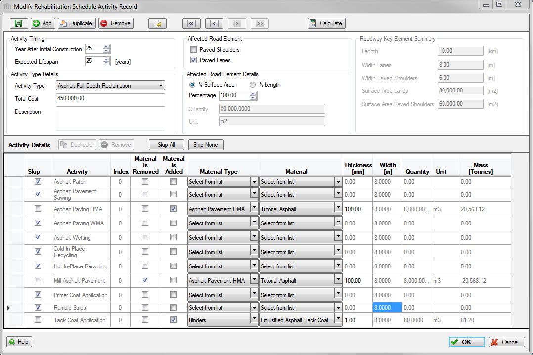
Full Depth Reclamation
- Still in the "Modify Rehabilitation Schedule Activity Record" form, click Add to save the "Rout & Seal" rehabilitation activity and to add a new rehabilitation activity
- Fill in the form as illustrated in the screen shot below.
- Click OK to save the "Full Depth Reclamation" rehabilitaton activity and close the "Maintain Rehabilitation Schedule Activity Record" form.
Your "Rehabilitation Schedule" table should appear as below.
When you're done, click OK to save the assembly.
You have now added a Maintenance and Rehabilitation Schedule to your roadway assembly.
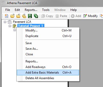
Add Extra Basic Materials
While the Pavement LCA offers a wide array of material and assembly combinations in some cases users may want to augment their project designs with additional materials. It should be noted that when you choose to add "Extra Basic Materials" the application doesn’t know how or where these materials are to be used. Hence, the LCA profile provided for extra basic materials is truncated in the sense that the application delivers the material to the construction site, but does not calculate any construction effects associated with material usage.
To add Extra Concrete to the project, right click on the Project [P] level node to activate the right click menu select "Add Extra Basic Materials" from the menu.
This opens the "Add Concrete" dialog. See the "Add or Modify Extra Basic Materials" help file for more details.
- Select "Concrete Pavement" from the "Material Type" dropdown list.
- Select "Concrete PC 30 MPa (flyash 9%)" from the "Materials" dropdown list.
- Click Add to add the selected material to the list of Extra Basic Materials.
- Enter "1" for the "Amount".
- Leave all other fields with their default 0.00 values.
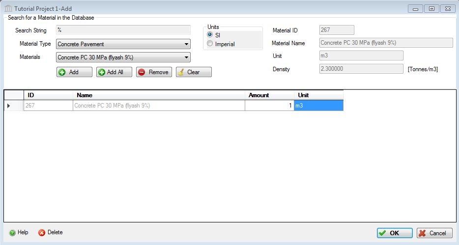
- Click the "OK" button to save the new Extra Basic Materials assembly.
Save the Project
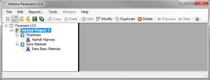
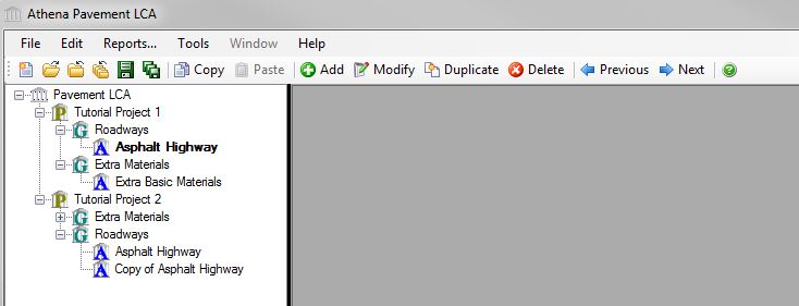
Now that Tutorial Project 1 has been created and a roadway and Extra Basic Materials have been added, the Tree Control Window will have a Project [P] level node for "Tutorial Project 1", two Assembly Group [G] level nodes corresponding to the Assembly Groups to which the two assemblies belong, and two Assembly [A] level nodes corresponding to each of thetwo Assemblies.
Select the "Tutorial Project 1" node, then select the "Save" button from the toolbar. Alternatively, you could Right click the Project [P] level node and select the "Save" menu option, or select "Save" from the "File" menu.
Generate Project Results
To view either the absolute inventory results (e.g.- Energy Consumption, Air Emissions, Water Emissions, Land Emissions, and Resource Use) or the eight aggregated summary impact measures – Fossil Fuel Consumption, Acidification Potential, Global Warming Potential, Human Health Criterial, Ozone Depletion Potential, Smog Potential, Eutrophication Potential – as a graph or table, you simply do the following:
- Right click one of the Project nodes. (Note: You can also start by selecting the "Reports" menu item from the "Main Menu")
- Select "Reports" from the "Project" menu. The "Reports" dialog will open to the "General" tab.
- Select a Report Format ("Graph" or "Table").
- Select a Format ("Absolute Values" or "Summary Measures").
- Select the Report Type ("By Life Cycle Stages").
- Select the "Summary Measure" effects or "Absolute Values" effects.
- Click on the "Bill of Materials" button to generate a BOM report.
- Click on the "Show Reports" button to generate the requested report(s).
See the "Reports Menu" help file for more information.
The "Reports" dialog has two tabs, "General" and "Comparison Graphs". The "Comparison Graphs" tab is only available if two or more projects are open.
The form on the "General" tab provides the user with options for generating one or more reports using either the absolute inventory results or the eight aggregated summary impact measures (e.g. - Fossil Fuel Consumption, Air Acidification, Global Warming Potential, Human Health Criteria, Ozone Depletion Potential, Smog Potential, and Eutrophication Potential) as a graph or table. This form can also be used to generate a "Bill of Materials" report.
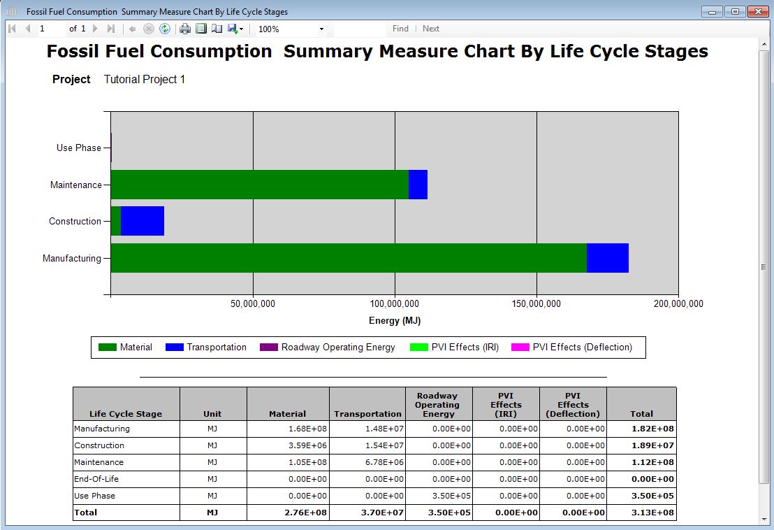
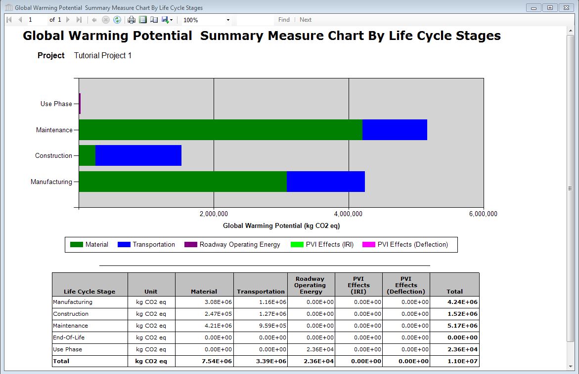
For the purposes of this tutorial, we will generate the "Bill of Materials" and "Summary Measures by Life Cycle Stage - Fossil Fuel Consumption and Global Warming Potential" reports.
Select the Project [P] level node for "Tutorial Project 1", right click and select "Reports" to open the "Reports" dialog. Alternatively, after selecting the "Tutorial Project 1" Project node in the tree, you could have selected "Reports" from the main menu.
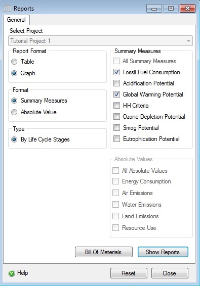
- Select "Graph" for the "Report Format".
- Select "Summary Measures" for the "Format".
- Select "By Life Cycle Stages" for the "Type".
- Select "Fossil Fuel Consumption" and "Global Warming Potential" from the list of "Summary Measures".
- Click the "Show Reports" button.
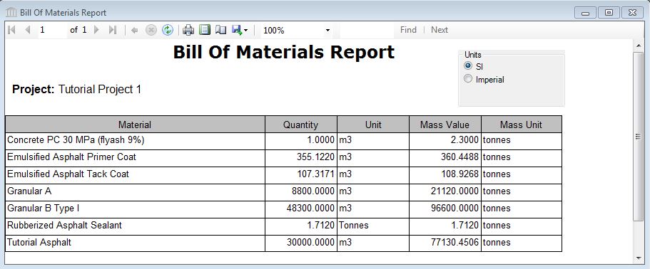
- Click the "Bill of Materials" button to generate the Bill of Materials for the project.
The three reports are displayed below.
TUTORIAL PROJECT 2
Duplicate Tutorial Project 1.
When you want to compare up to 5 projects, or if you have a single project and want to compare the effects of one or more changes, you can duplicate the entire project, make some changes, then run comparison reports. In this section, titled "Tutorial Project 2", we will duplicate "Tutorial Project 1", make a few changes, then save the project. In the "Comparison Reports" section, we will run some comparison reports to see some of the differences between the two projects.
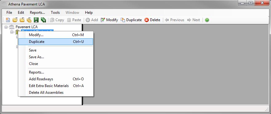
- In the Tree Control, Select the Project [P] level node for "Tutorial Project 1".
- Right Click and select
"Duplicate" from the menu. Alternatively, you
could have selected the project node, and then clicked the "Duplicate"
button in the Toolbar.
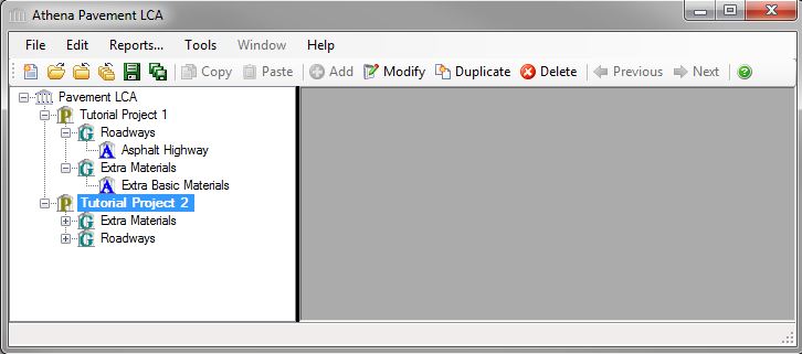
- A new Project [P] level node will be
added to the Tree Control Window. By default, the new project will be
named "Copy of Tutorial Project 1" Lets rename the new project. Double
click the new project node (alternatively you could
Right click the new project node and select "Modify" from the menu).
This will open the "Modify Project" dialog. Change the
"Project Name" to "Tutorial Project 2" then click the "OK"
button.
Change the Length of Apshalt Highway.
Lets halve the length of Asphalt Highway in Tutorial Project 2
- Show the "Assembly Groups" by selecting the plus sign (+) beside the Project [P] level node for Tutorial Project 2.
- Show the "Asphalt Highway" assembly by selecting the plus sign (+) beside the Assembly Group [G] level node for the "Roadways" assembly group.
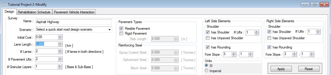
- Open the "Asphalt Highway" dialog by double clicking the Assembly level node for the "Asphalt Highway" assembly.
- Change the "Lane Length" value from 10 km to 5 km.
- Click Apply to apply the change to the roadway design elements.
- Click OK to accept the change and close the dialog.
Copy an Assembly Between Projects
Another time saving feature is the ability to copy an entire assembly, including its rehabilitation schedule to the same or another open project. In this section, you will copy the "Asphalt Highway" roadway from Tutorial Project 1 into Tutorial Project 2.
- Show the "Assembly Groups" by selecting the plus sign (+) beside the Project [P] level node for Tutorial Project 1.
- Show the "Roadways" assembly by selecting the plus sign (+) beside the Assembly Group [G] level node for the "Roadways" assembly group.
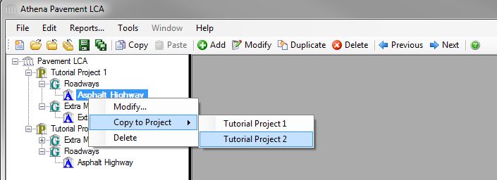
- Right click the
Assembly [A] level node for the "Asphalt Highway" assembly,
select "Copy to Project", then select "Tutorial Project 2".
Alternatively, you could have selected the "Asphalt Highway"
assembly node, picked the "Copy" toolbar button, selected the "Tutorial
Project 2" project node, then picked the "Paste" toolbar button.
The "Tree Control Window" will now contain nodes for both projects and all of their assembly groups and assemblies.
- Let’s rename the new copied roadway and make some other changes.
- Double click the Assembly [A] level node for the "Copy of Asphalt Highway" to lauch the "Modify Roadway" dialog.
- In the Roadway Cross Section section, make the following changes:
- Name to Concrete Highway,
- Lane Length to 5 km,
- # Pavement Lifts to 1,
- Select the "Rigid Pavement" checkbox
- (leave "Flexible Pavement" selected, we’re assuming the shoulders are paved with asphalt),
- Slab Length to 4.5 m,
- Enter 10 tonnes of Galvanized for Reinforcing Steel (For dowels and tie bars, total must be calculated separately)
- Click Apply to regenerate the Roadway Cross Section and Design Details.
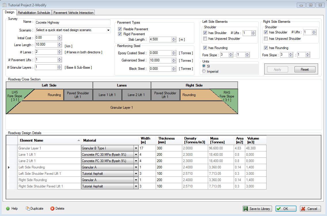
- In the Roadway Design Details section, make the following changes:
- Change the Material Type for lanes 1 and 2 to Concrete PC 30 MPa (flyash 9%)
- Change the thicknesses for all lane and shoulder lifts to 200 mm.
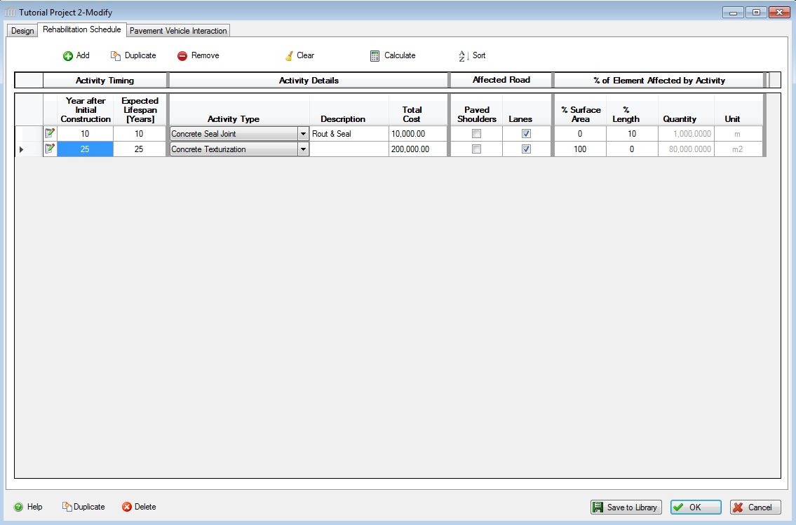
- Click on the "Rehabilitation Schedule" tab.
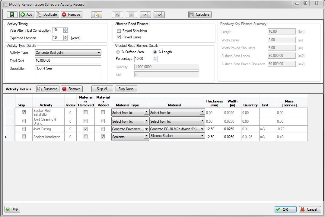
- Click the Edit button for the Asphalt Rout & Seal activity.
- Change the form details as shown in the following screen shot.
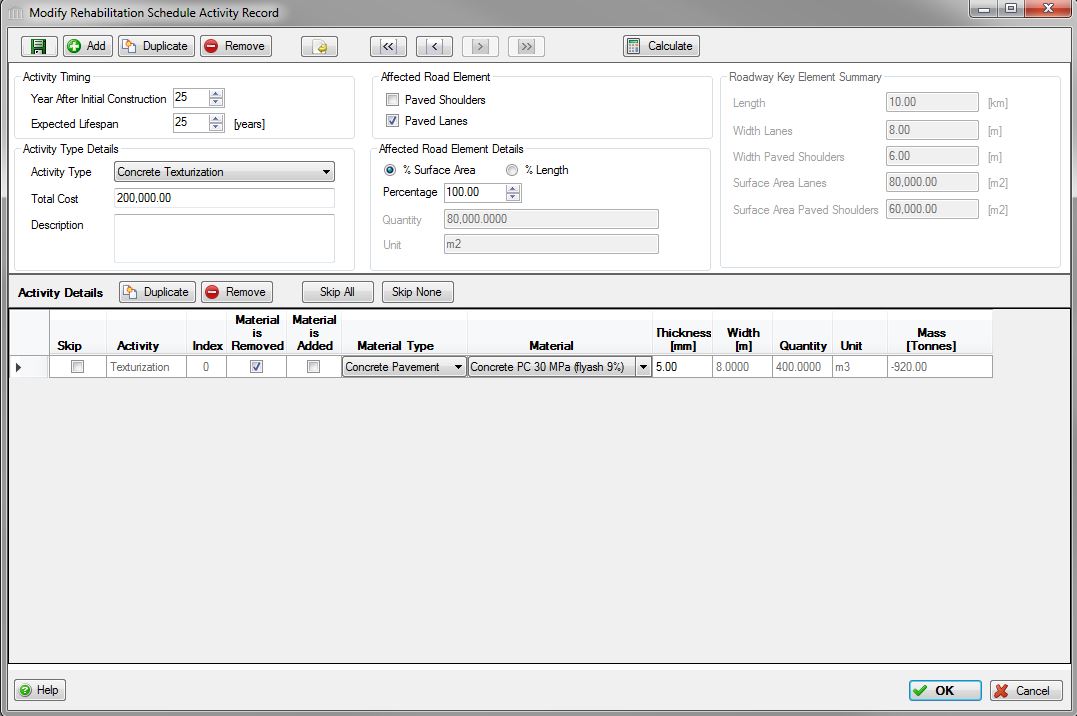
- Click the Next button to save the changes and navigate to the next record, in this case the Asphalt Full Depth Reclamation activity.
- Change the form details as shown in the following screen shot.
- Click OK to accept the changes to the assembly.
- Click Ok to save the Roadway design.
- Save Tutorial Project 2.
- Select the "Tutorial Project 2" node to activate the second project.
- Select the "Save" button from the toolbar. Alternatively, you could Right click the Project [P] level node and select the "Save" menu option, or select "Save" from the "File" menu.
Your "Rehabilitation Schedule" table should appear as below.
Generate Project Results
For the purposes of this tutorial and so that you can see the differences between the Bill of Materials for the two projects, we will generate the "Bill of Materials" reports.
Select the Project [P] level node for "Tutorial Project 2", right click and select "Reports" to open the "Reports" dialog. Alternatively, after selecting the "Tutorial Project 2" Project node in the tree, you could have selected "Reports" from the main menu. See the "Reports Menu" help file for more information.
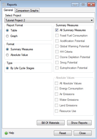
- Click the "Bill of Materials" button to generate the Bill of Materials for the project.
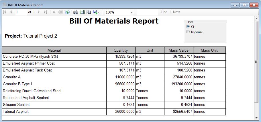
Take a moment to compare the "Bill of Materials" reports for the two projects. If you are interested, you can export each report to Excel and do even more extensive comparison and analysis there.
COMPARISON REPORTS
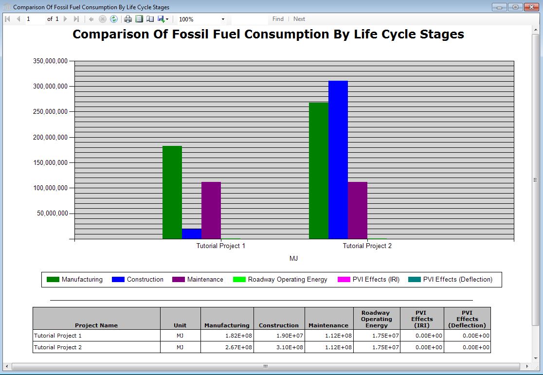
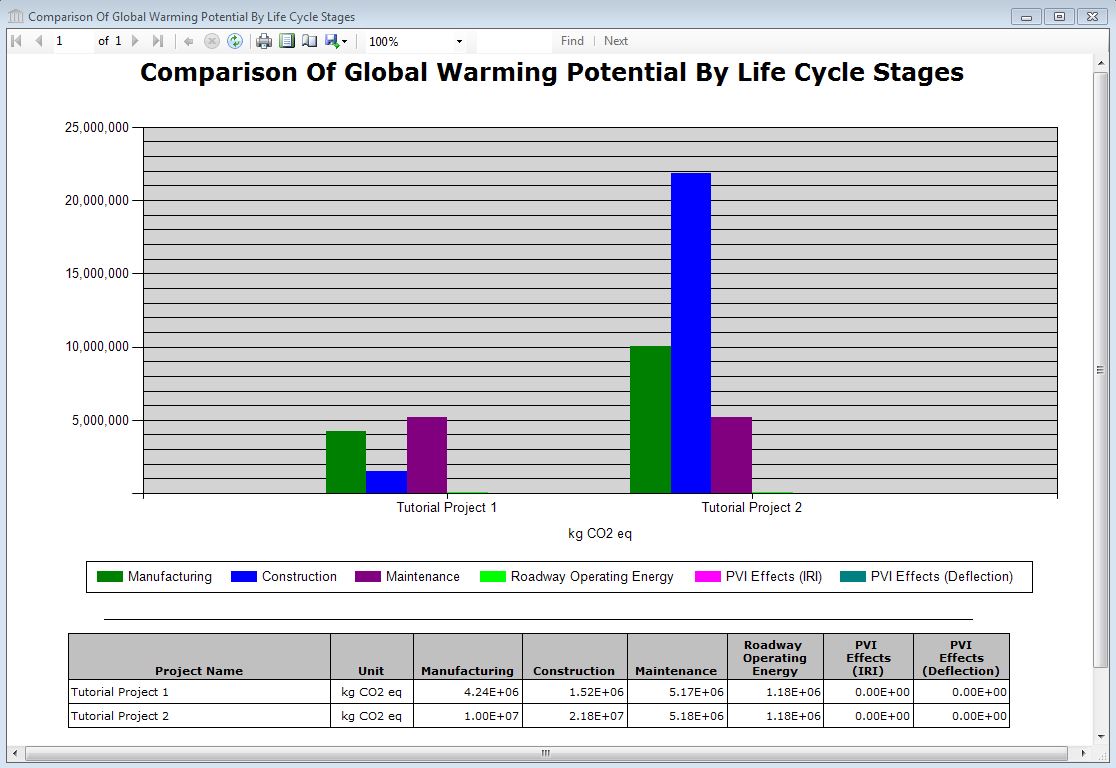
Generate Comparison Reports (Fossil Fuel Consumption, GWP)
Accommodating up to five comparisons at once, Pavement LCA allows users to change the design, substitute materials, and make side-by-side comparisons for any one or all of the environmental impact indicators. Or compare the new roadway design to one you did last year. You can also compare similar projects with different lengths/widths on per m2 basis. Pavement LCA can perform as many as five project comparisons at a time.
From a reporting perspective, all Pavement LCA results are compiled and accessed at the project level. So if you are interested in comparing two or more assemblies, rather than complete designs, you must input each assembly you want to compare as an individual project. To properly use the compare utility you need to have two or more Projects opened. See the "Reports Menu" and "Generate Reports - Multi-Project Comparison Graphs" help files for more information. If you have been following along with the tutorial thus far, you presently have "Tutorial Project 1" and "Tutorial Project 2" open.
To compare the two projects, do the following:
- Right click one of the Project nodes. Alternatively, you can also start by right clicking one of the Project Nodes or by selecting the "Reports" menu item from the "Main Menu".
- Select "Reports" from the "Project" menu. The "Reports" dialog will open to the "General" tab. Click on the "Comparison Graphs" tab.
- Select the checkboxes for "Tutorial Project 1" and "Tutorial Project 2" in the list of open projects under the "Select Project(s)" label. Note: For each project that you wish to compare, double-click on the corresponding entry in the "Selected Project" list.
- From the list of "Summary Measures", select "Fossil Fuel Consumption" and "Global Warming Potential".
- Select the "Absolute Value" for the report results "Format". Later if you wish, you can use one of the selected projects as a baseline, you can pick it from the "Project Baseline" selection list.
- Select "Life Cycle
Stage" for the report "Type".
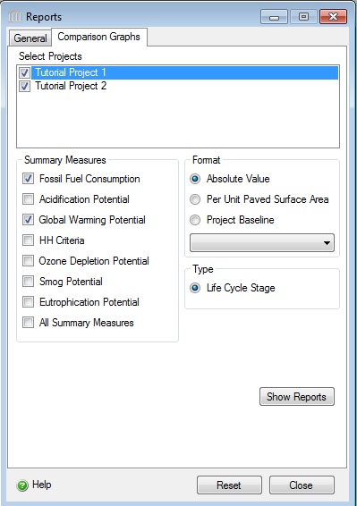
- Click the "Show
Reports" button.
SAMPLE PROJECTS
Open the Sample Case Study Project Files
By now you should be familiar with the basic operations of the Pavement LCA. You are now ready to begin entering a new project of your choice. For your reference, the two tutorial projects are included with the initial installation of the Pavement LCA:
- Tutorial Project 1
- Tutorial Project 2
The Sample Project files are located on your hard drive in the
following folder:
C:\Documents and Settings\USERNAME\My
Documents\Athena\Pavement LCA\Sample Projects (Windows XP)
C:\Users\USERNAME\Documents\Athena\Pavement LCA\Sample Projects (Windows Vista or Windows 7)
ENJOY!