Impact Estimator for Buildings - Tutorial
Overview
In this tutorial, we attempt to introduce you to a number of features of the Impact Estimator for Buildings version 4, focusing on those aspects of the software that you will use every time you start it up.
The tutorial has been broken into sections in order to make it easier to follow and to help make it a useful reference.
Here is a brief outline of what we will be covering:.
SECTION 1: INTRODUCTION
SECTION 2: GENERAL
- Set Application Options.
- Add a Reusable Predefined Envelope System - Double Wood Stud Exterior Wall Envelope.
SECTION 3: PROJECT #1
- Create a Project - name it "Project 1".
- Enter Operating Energy Consumption.
- Add a Columns & Beams Assembly.
- Add a Custom Wall Assembly – Double Wood Stud Wall.
- Define the Envelope for the Custom Wall.
- Define the Envelope for the Custom Wall using a Predefined Envelope System.<
- Add Extra Basic Materials - Concrete.
- Save the Project.
- Generate Project Results.
SECTION 4: PROJECT #2
- Duplicate the Project - rename it "Project 2".
- Modify the Double Wood Stud Wall Assembly from "Project #1".
- Edit the Envelope, change the insulation to "Rockwool Batt".
- Copy the Columns & Beams Assembly from "Project #1" into "Project #2", rename it and change both the "Column Type" and "Beam Type" to "Concrete".
- Generate a Bill of Materials for "Project #2".
SECTION 5: COMPARISON REPORTS
- Generate Comparison Reports.
SECTION 6: SAMPLE PROJECTS
- Open the Sample Case Study Project Files.
Introduction
Introduction to Using the Athena Impact Estimator for Buildings 4
This self-guided tutorial describes how the application works from a user’s perspective, with illustrations of some of the screens, dialog boxes and tool bars as well as a discussion of some other application features. You can choose to either just read through the following passages or follow along by actually duplicating some of the example input screens presented – as we all learn more quickly by doing, we highly recommend the latter.
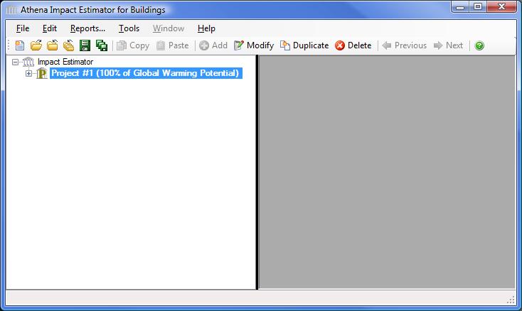
When you first open the Impact Estimator application, a familiar Application Program menu bar, the "Main Menu", appears immediately under the Athena Impact Estimator window title bar. The "Main Menu" consists of File, Edit, Reports, Tools, Window, Help submenus. Located under the "Main Menu" is a set of familiar icons in the "Toolbar". When the software is first started up, the toolbar can be used to initiate project assessments by either creating a new project input file or opening an existing (previously saved) project input file. See the "Impact Estimator Menus" help file for more information.
As with most application programs, you can use the File menu to either create a New project input file or Open a previously saved project input file. You can also click on the first icon (reading left-to-right) to create a new project input file or click on the second icon to open a previously saved project input file. By default, all saved project input files reside in the main Impact Estimator folder unless you select another directory/folder pathway when executing a "Save As" file operation. We recommend that you save project input files to a folder in your "My Documents" (Windows XP), "Documents" (Windows Vista or Windows 7) or similar folder that is not located within the "Program Files" folder.
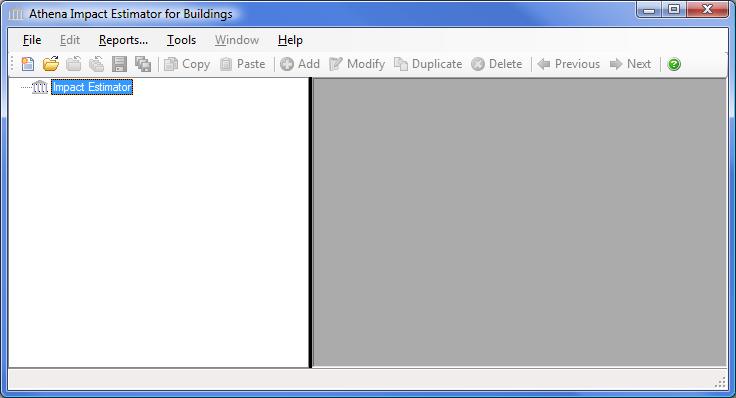
Immediately below the icon toolbar you will see the Impact Estimator Tree Control window which operates as a hierarchical viewer of all inputs into the application; allowing you to create and compare projects, insert assemblies, track (review) your design (assembly) inputs and edit (modify) them. Essentially the Impact Estimator Tree Control window allows you to perform the logic operations offered on the main menu bar. For example, within the Impact Estimator Tree Control window you will see the Impact Estimator’s Root Node highlighted (Impact Estimator). With your mouse pointer on the highlighted Root Node "right click" to activate a new vertical menu list (also referred to as the "right click menu"). From here you can create a New project, Open a previously saved project, Save all active projects, Close all active projects and a number of other operations. See the "Using the Impact Estimator Tree Control Window" help file for more information.
The following sections will describe the input and output operations using the Impact Estimator Tree Control window as the primary method for navigating through the application.
Please note that the software is packaged with a context sensitive HELP file, which provides detailed directions for inputting designs and interpreting results. Click here to access the main help file.
GENERAL
Set Software Options
Click the "Tools" main menu option to display the "Tools" submenu.
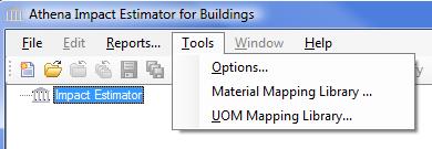
Click "Options" to open the "Options" dialog. The "General" tab of the "Options" dialog provides the user with the opportunity to set some application behaviour preferences. Selecting the "Options" menu item from the "Tools" menu opens the "General" tab of the "Options" dialog. See the "Options - General" help file for more details.
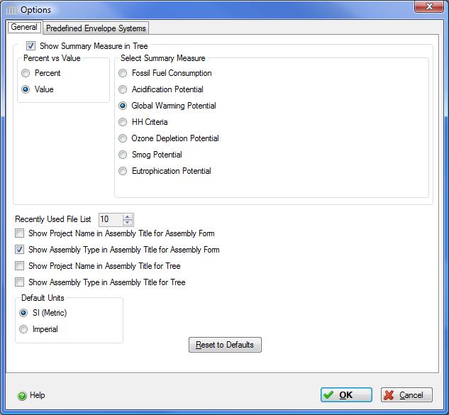
The Impact Estimator Tree Control Window may be configured to display one of the LCA measures for a project as either a percent or actual value for the embodied effects. The embodied effects are due entirely to project assemblies with no contributions due to by the project Operating Energy.
To enable this feature, select "Show LCA Measure in Tree", the "Percent" radio button and the "Global Warming Potential" radio button.
Continue making changes to the "Options" form so that your "Options" are the same as those above. If you prefer to work in "Imperial" units, make sure that you select the "Imperial" Default Units radio button.
Add a Reusable Predefined Envelope System
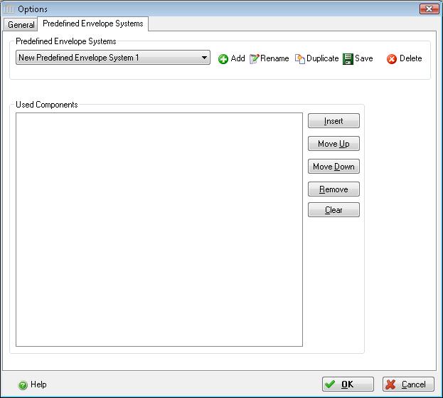
New to version 4.1 is the ability to define complete envelope systems, save them, and then reuse them on any project. The "Predefined Envelope Systems" tab of the "Options" dialog provides the user with this opportunity.
To access the "Predefined Envelope Systems " form, Click the "Tools" main menu option to open the "Options" dialog, then click on the "Predefined Envelope Systems" tab.
See the "Options - Predefined Envelope Systems " help file for more details.
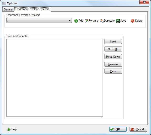
Follow these steps to create a new envelope system:
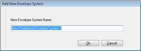
- Click the "Add New Envelope System "
 to create a new envelope system. The new envelope system will be named "New Predefined Envelope System # " or where # is blank or an integer (1, 2, 3, ...).
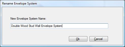
- Select the "New Envelope System ", click the
 "Rename" button to open the "Rename Envelope System" form, enter a new name (e.g., "Double Wood Stud Wall Envelope System ") and click the "OK" button.
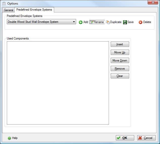
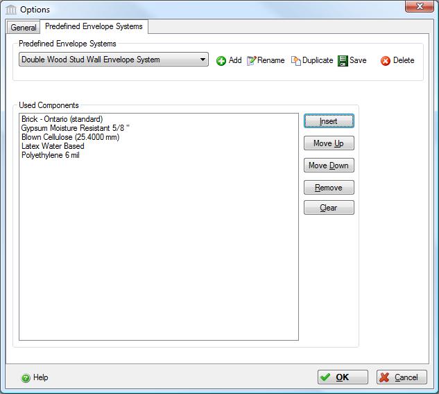
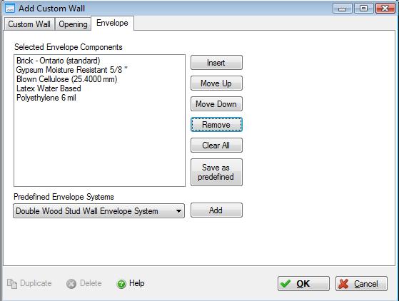
Follow these steps to add envelope layers to the new "Double Wood Stud Wall Envelope System":
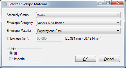
- Click the "Insert" button to open the "Select Envelope Material" dialog.
- Change the "Assembly Group" to be "Walls".
- Set the "Envelope Category" to "Cladding".
- Select "Brick - Ontario (standard)".
Note that the plywood sheathing can be added using the "Wood Stud Wall Assembly" dialog.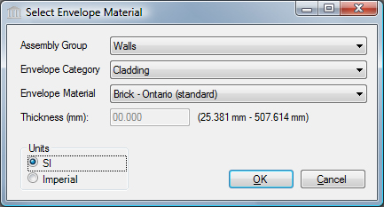
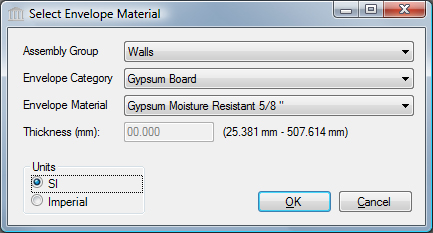
- Change "Envelope Category" to "Gypsum Board", select "Gypsum Moisture Resistant 5/8 in"
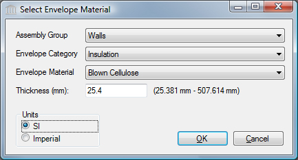
- Change "Envelope Category" to "Insulation", select "Blown Cellulose" and set the "Thickness" to 25.4 mm.
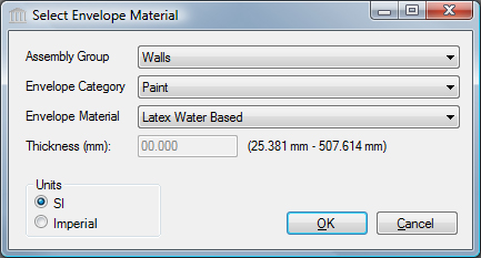
- Change "Envelope Category" to "Paint", select "Latex Water Based".
- Change "Envelope Category" to "Vapour & Air Barrier ", select "Polyethylene 6 mil ".
You have now defined a "Reusable Predefined Envelope System". We will soon be using this envelope system when we create a new double wood stud wall assembly in Project #1.
PROJECT #1
Create a New Project
Now you can create a new project. Immediately below the toolbar you will see the Impact Estimator Tree Control window, which operates as a hierarchical viewer of all inputs into the model. Within the Tree Control window you will see the Impact Estimator Root node highlighted. With your mouse pointer on the highlighted Root node, "right click" to activate a new vertical menu list (also referred to as the right click menu). Click-on "New Project" in the right click menu to open the "Add Project" dialog box. Alternatively, you can click on the ![]() "New" button on the far left side of the toolbar to open the "Add Project" dialog box
"New" button on the far left side of the toolbar to open the "Add Project" dialog box
Here, you are asked to enter some general information about the project to be modeled. You can either navigate through the dialog box using your tab key or by simply using your mouse pointer to toggle various “radio buttons” or enter text, where appropriate. Note that you must enter a project name, project location, building life, and building/occupancy type – all other information, including annual operating energy values, is optional. When you are finished adding project information, click the “OK” button to save the changes and close the “Add Project” dialog. A new Project [P] level node with the title you gave the project will be added to the Tree Control immediately under the Root node. See the "Add or Modify a Project" help file for more details.
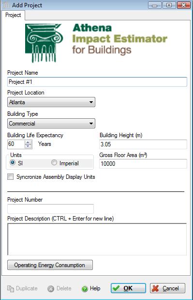
As in the image above, enter the following information:
- For the "Project Name", enter "Project #1".
- Select "Atlanta" from the "Project Location" list.
- Select "Commercial" from the "Building Type" list. This descriptor is used to invoke the default maintenance and replacement schedule for that building type.
- Enter 60 years for the for the "Building Life Expectancy". This invokes typical envelope component maintenance and replacement schedules which is keyed to the building location, type and its life expectancy. You may choose to either select and enter the building life or use the scrolling arrows to change the building life by increments of 20 years. The building life is also used to determine the total life cycle operating energy should you choose to enter the annual operating energy by fuel type.
- For the "Units", select the "SI" radio button. This is the default Units that you want the application to use when opening dialog boxes for data input and reporting bill of material quantities. The SI (metric) unit designation is the default for entering assembly information. While the inputs to the application can be specified as either US Imperial or (SI) metric, the internal application working units are metric and final results are also presented in metric units.
- Enter 3.05 m for the "Building Height".
- Enter 10,000 m2 for the "Gross Floor Area". This value can be used to have the results summarized on a unit floor area basis. The remainder of this tutorial assumes that you selected the Select the "SI" radio button.
Both the "Project Name" and "Project Location" are two pieces of information that must be entered because they activate a number of critical functions in the application.
Enter Operating Energy Consumption
The "Operating Energy Consumption" button on the "Add Project" form opens another window and allows you to input annual operating energy for the building by fuel type (this is another optional input). It is assumed that this operating energy information would come from another simulation tool. The application takes this energy information and converts it to primary energy and calculates related emissions to air, water and land. Later the user may then compare and contrast embodied and operating energy and emissions within and between up to 5 projects. If your operating energy output is in MJ or BTUs rather than physical units of fuel, simply click on the compute fuel button next to the fuel of interest to have the application convert the fuels energy value into physical units. The application then automatically calculates and enters this quantity of fuel in the Building Operating Energy Consumption table. See the "Building Operating Energy Consumption" help file for more detailed instructions on using the compute fuel conversion.
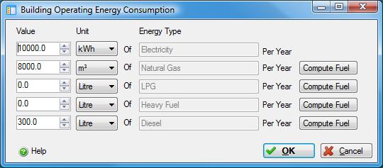
As in the image above, enter the following information:
- Enter 10,000 kWh of Electricity,
- Enter 8,000 m3 of Natural Gas, and
- Enter 300 Litres of Diesel.
Once the initial project descriptors have been selected, click on the "OK" button to save the information and exit the dialog box. Click the "Cancel" button to discard the new project. In the Impact Estimator Tree Control window you will now see a plus sign (+) in front of the Root Node. By clicking on the plus sign a Project [P] level object will appear with the title "Project # 1". You have now successfully created a new project.
Defining an Assembly Overview
Now you are ready to start adding Building Structural Elements (Assemblies) to the project. To define an assembly, right click on the Project [P] level node to activate the right click menu and select “Add Assembly” from the menu. A listing of various assembly groups will appear – Foundations, Walls, Columns and Beams, Roofs, Floors, and Extra Basic Materials. Select an assembly group to display the assembly group submenu, then select the assembly of interest to you.
An “Add Assembly” dialog will appear for the assembly that you selected. The flashing cursor will automatically be placed in the “Name” box. Each assembly must first be given a name; otherwise no data input is possible. After entering an assembly name (e.g., North Wall ), tab to each of the data input boxes or, using your mouse, place the cursor in each to describe the assembly’s geometry and attributes.
Continue using the “Add Assembly” menu as necessary to complete the structural elements for a three-dimensional building space.

After entering the assembly details and clicking the "OK" button, the assembly dialog box will close and a new plus sign [+] will appear beside the Project [P] level object in the Tree Control Window.
If you click on the [+] sign you will cascade to the Assembly Group Node, clicking on the [+] sign beside the Assembly Group takes you to the a list of Assembly Nodes. Double clicking on an Assembly Node will open the "Modify Assembly" dialog. Wall Assemblies, consisting of one or more assembly components (sub-assemblies), is a special Assembly Node and is the only Assembly Node that has a [+] beside it. Clicking on the [+] beside the Wall Assembly Node will display the list of wall components used to define the wall assembly. Please note that since each wall component (sub-assembly) lacks any meaning without its parent wall assembly, nothing will happen if you double click on a wall component in the Tree Control.
Add a Columns & Beams Assembly
To define a Columns & Beams assembly, right click on the Project [P] level node to activate the right click menu and select “Add Assembly” from the menu. Select the "Columns & Beams" assembly group, then select "Columns & Beams" from the menu. This opens the "Add Columns & Beams Assembly" dialog. See the "Add or Modify a Columns & Beams Assembly" help file for more details.
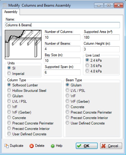
Enter the following into the "Add Columns and Beams Assembly" dialog:
- Enter "Columns & Beams" for the Assembly "Name".
- Enter "10" for the "Number of Columns".
- Enter "4" for the "Number of Beams".
- Enter "10.0 m" for the "Bay Size".
- Enter "6.0 m" for the "Supported Span".
- Enter "3.0 m" for the "Column Height".
- Enter "180.0 m2" for the "Supported Area".
- Click the "OK" button to save the new "Columns and Beams" assembly and close the dialog.
Add a Custom Wall Assembly – Double Wood Stud Wall
New to version 4 is the ability to combine multiple wall "component" sub-assemblies into a single "custom wall" assembly. You can think of a "custom wall" assembly as a container into which one or more similar or different types of wall "component" sub-assemblies are added.
To define a Custom Wall assembly, right click on the Project [P] level node to activate the right click menu and select “Add Assembly” from the menu. Select the "Walls" assembly group, then select "Custom Wall " from the menu. This opens the "Add Custom Wall Assembly" dialog. See the "Add or Modify a Custom Wall Assembly" help file for more details.
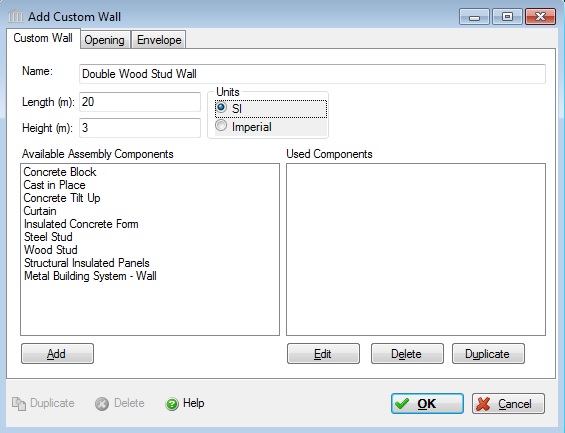
Enter the following into the "Add Custom Wall Assembly" dialog:
- Enter "Double Wood Stud Wall" for the Assembly "Name".
- Enter "20.0 m" for the "Length"
- Enter "3.0 m" for the "Height"
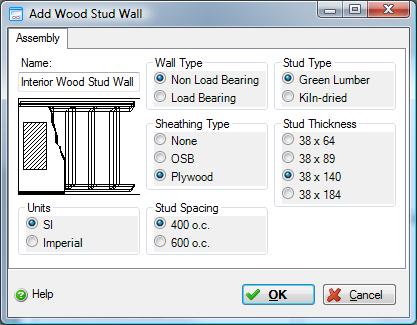
- In the "Available Assembly Components" list, double click on the "Wood Stud" to add the Exterior Wood Stud Wall. Complete the "Add Wood Stud Wall" form with the information as it appears in the following image.
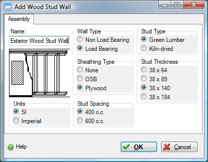
- In the "Available Assembly Components" list, double click on the "Wood Stud" again, this time to add the Interior Wood Stud Wall. Complete the "Add Wood Stud Wall" form with the information as it appears in the following image.
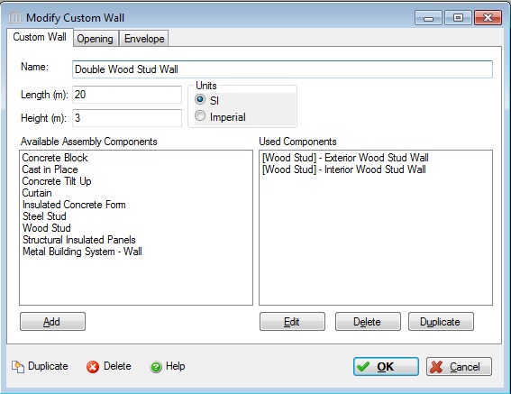
The "Add Custom Wall" assembly form will now have the following appearance:
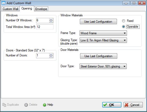
- Openings: Click on the "Opening" tab to edit the assembly specific opening details. For windows, you can enter the number of window openings, the total window opening area, window frame materials, window glazing type, and whether the windows are fixed or operable. For doors, you can enter the number of door openings and the door type. See the "Define Window and Door Openings" help file for more information.
One caveat is that you can only define a single window type and/or door type for each wall assembly object.
Fill out the form on the "Opening" tab with the information as it appears in the following image.
- Envelope: For certain assembly types (i.e., Walls, Floors, Roofs, or Foundations), users can choose to "Define the Envelope" materials . Essentially, the user now specifies the sandwich make-up of the assembly . Each element of the envelope is defined by selecting the envelope category, envelope material and thickness (where applicable). Once selected the user clicks on the "Add" button to add the specific element to the envelope definition sandwich. See the "Define an Assembly Envelope" help file for more information.
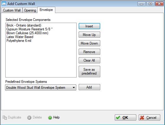
- Add Cladding to the Envelope:
- Click the "Insert" button to open the "Select Envelope Material" dialog.
- Change the "Assembly Group" to be "Walls.
- With "Envelope Category" set to "Cladding", select "Brick - Ontario (standard)".
Note that the plywood sheathing can be added using the "Wood Stud Wall Assembly" dialog. - Click the "OK" button.
- Add Gypsum Board to the Envelope:
- Click the "Insert" button to open the "Select Envelope Material" dialog.
- Change "Envelope Category" to "Gypsum Board", select "Gypsum Moisture Resistant 5/8 in"
- Click the "OK" button.
- Add Insulation to the Envelope:
- Click the "Insert" button to open the "Select Envelope Material" dialog.
- Change "Envelope Category" to "Insulation", select "Blown Cellulose" and set the "Thickness" to 25.4 mm.
- Click the "OK" button.
- Add Paint to the Envelope:
- Click the "Insert" button to open the "Select Envelope Material" dialog.
- Change "Envelope Category" to "Paint", select "Latex Water Based" .
- Click the "OK" button.
- Add Vapour & Air Barrier to the Envelope:
- Click the "Insert" button to open the "Select Envelope Material" dialog.
- Change "Envelope Category" to "Vapour & Air Barrier ", select "Polyethylene 6 mil " .
- Click the "OK" button.
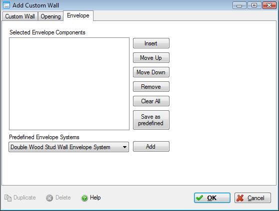
- Clear All of the Envelope Components:
- Click the "Clear All" button to remove all of the "Selected Envelope Components" that you just finished adding.
- As an alternative to defining an envelope for an assembly, you could have selected the "Predefined Envelope System" list and picked the "Double Wood Stud Wall Envelope System" that you created earlier.
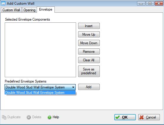
- Click the "Add" button to add the envelope components from the reusable predefined "Double Wood Stud Wall Envelope System" into the "Envelope Definition" for the "Double Wood Stud Wall" assembly.
- Our double wood stud wall has two 2"x6" wood stud walls. The amount of insulation in the reusable predefined "Double Wood Stud Wall Envelope System" is not sufficient to fill the cavity of this wall, so let's add more insulation. Click the "Insert" button to open the "Select Envelope Material" dialog and add "254.6 mm" of "Blown Cellulose" insulation. In the "Used Components" list, select the new insulation layer and click on the "Move Up" button twice. The "Envelope" form will now have the following appearance:
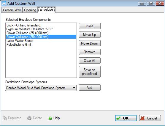
- Click the "OK" button to save the new "Double Wood Stud Wall" assembly with its openings and envelope system.
Please remember that when adding envelope materials you are adding individual layers to the sandwich. In the case of a partition wall having painted gypsum board on both sides of the wall, you would therefore need to add gypsum wall board and paint twice.
Click on the "Envelope" tab to edit the assembly specific envelope details. You can insert new envelope materials and change their ordering in the envelope sandwich.
Follow these steps to add envelope layers to the new "Double Wood Stud Wall Assembly":
You have now defined an "Envelope System".
Add Extra Basic Materials
While the Impact Estimator offers a wide array of material and assembly combinations in some cases users may want to augment their project designs with additional materials. It should be noted that when you choose to add "Extra Basic Materials" the application doesn’t know how or where these materials are to be used. Hence, the LCA profile provided for extra basic materials is truncated in the sense that the application delivers the material to the building site, but does not calculate any construction effects associated with material usage.
To add Extra Material to the project, right click on the Project [P] level node to activate the right click menu and select "Add Assembly" from the menu. Select the "Extra Basic Materials" assembly group, then select "Extra Materials " from the menu. This opens the "Add Extra Materials " dialog. See the "Add or Modify Additional Materials" help file for more details.
- Enter "1000 m3" for "20 MPa Average Flyash".
- Enter "1000" for "Concrete/Masonry Blocks".
- Enter "1000 m3" for "Mortar".
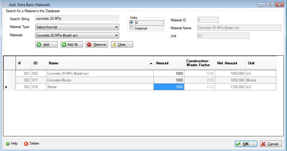
- Click the "OK" button to save the new "Extra Basic Materials " assembly.
Save the Project
Now that Project #1 has been created and a few assemblies have been added to the new project, the Tree Control Window will have a Project [P] level node for "Project #1", three Assembly Group [G] level nodes corresponding to the Assembly Groups to which the three assemblies belong, and three Assembly [A] level nodes corresponding to each of the three Assemblies.
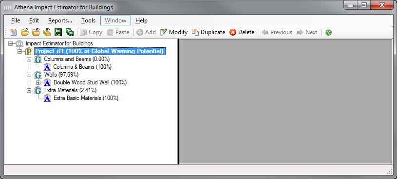
Select the "Project #1" node, then select the "Save" button from the toolbar. Alternatively, you could Right click the Project [P] level node and select the "Save" menu option, or select "Save" from the "File" menu.
Generate Project Results
To view either the life cycle inventory results (e.g.- Energy Consumption, Air Emissions, Water Emissions, Land Emissions, and Resource Use) or the nine aggregated LCA measures – Total Primary Energy Consumption , Non-Renewable Energy Consumption Fossil Fuel Consumption, Acidification Potential, Global Warming Potential, Human Health Particulate, Ozone Depletion Potential, Smog Potential, Eutrophication Potential – as a graph or table, you simply do the following:
- Right click one of the Project nodes. (Note: You can also start by selecting the "Reports" menu item from the "Main Menu")
- Select "Reports" from the "Project" menu. The "Reports" dialog will open to the "General" tab.
- Select a Report Format ("Graph" or "Table").
- Select a Format ("Life Cycle Inventory Results" or "LCA Measures").
- Select the Report Type ("By Life Cycle Stages", "Assembly Group Embodied Effects", "Operating Vs Embodied").
- If the Report Format is "Graph" or the Report Type is "Assembly Group Embodied Effects", select a System Boundary ("A-C" or "A-D")
- Select the "LCA Measure" effects or "Life Cycle Inventory Results Table" effects.
- Click on the "Bill of Materials" button to generate a BOM report.
- Click on the "Show Reports" button to generate the requested report(s).
See the "Reports Menu" help file for more information.
The "Reports" dialog has two tabs, "General" and "Comparison Graphs". The "Comparison Graphs" tab is only available if two or more projects are open.
The form on the "General" tab provides the user with options for generating one or more reports using either the life cycle inventory results or the nine aggregated LCA measures (e.g. -Total Primary Energy Consumption , Non-Renewable Energy Consumption Fossil Fuel Consumption, Acidification Potential, Global Warming Potential, Human Health Particulate, Ozone Depletion Potential, Smog Potential, Eutrophication Potential) as a graph or table. This form can also be used to generate a "Bill of Materials" report.
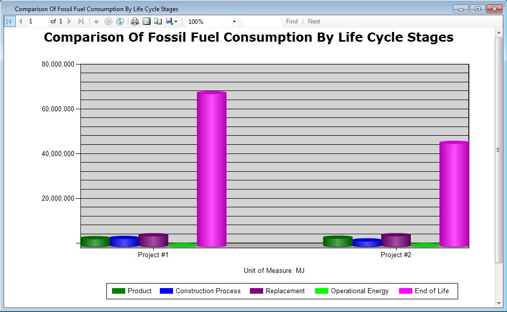
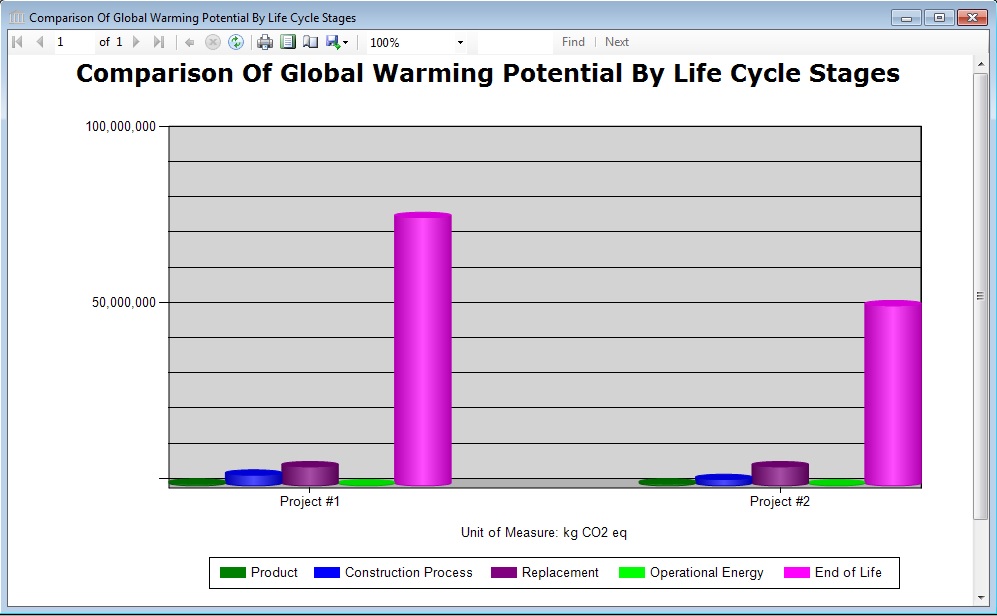
For the purposes of this tutorial, we will generate the "Bill of Materials" and "LCA Measures by Life Cycle Stage - Fossil Fuel Consumption and Global Warming Potential" reports.
Select the Project [P] level node for "Project #1", right click and select "Reports" to open the "Reports" dialog. Alternatively, after selecting the "Project #1" Project node in the tree, you could have selected "Reports" from the main menu.
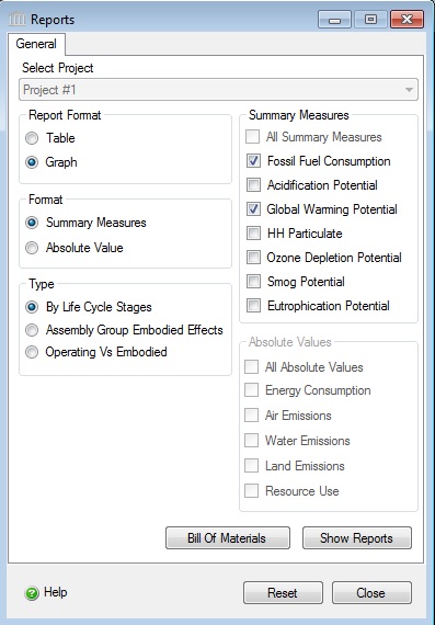
- Select "Graph" for the "Report Format".
- Select "LCA Measures" for the "Format".
- Select "By Life Cycle Stages" for the "Type".
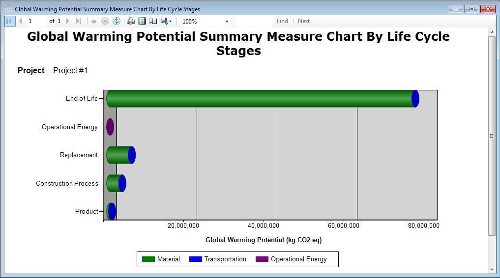
- Select "Fossil Fuel Consumption" and "Global Warming Potential" from the list of "LCA Measures".
- Click the "Show Reports" button.
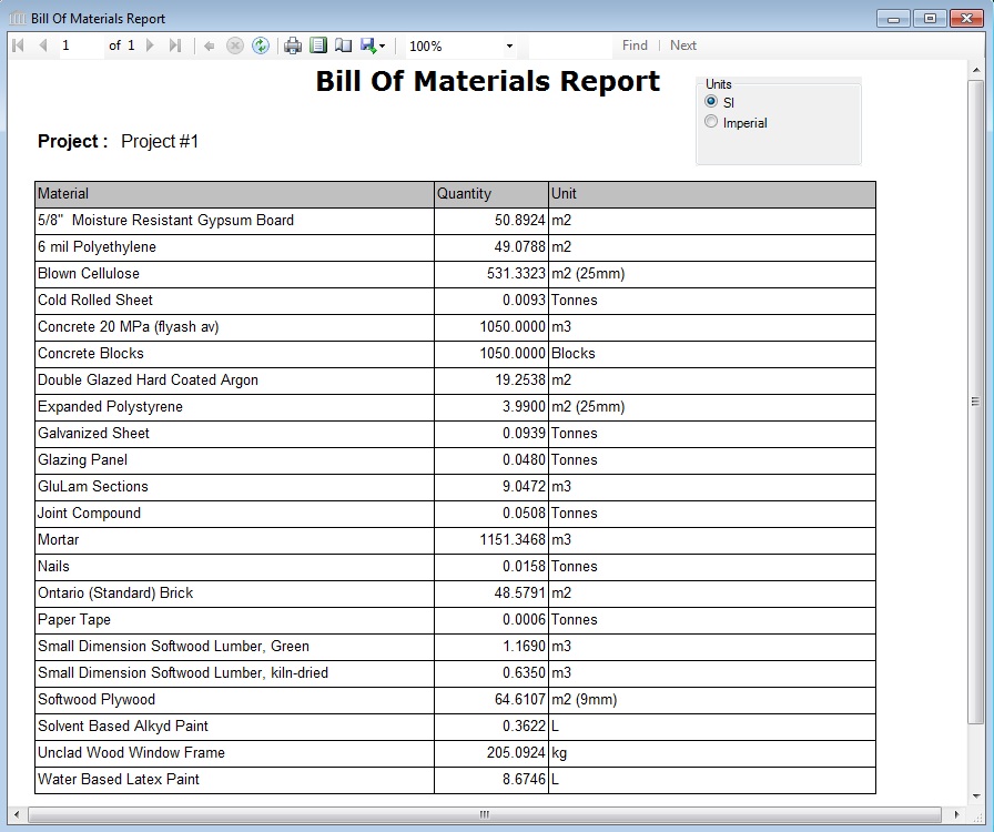
- Click the "Bill of Materials" button to generate the Bill of Materials for the project.
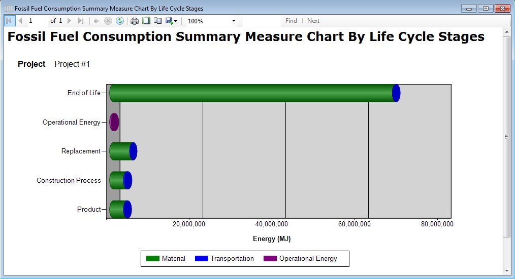
The three reports are displayed below.
PROJECT #2
Duplicate Project #1.
When you want to compare up to 5 projects, or if you have a single project and want to compare the effects of one or more changes, you can duplicate the entire project, make some changes, then run comparison reports. In this section, titled "Project #2", we will duplicate "Project #1", make a few changes, then save the project. In the "Comparison Reports" section, we will run some comparison reports to see some of the differences between the two projects.
- In the Tree Control, Select the Project [P] level node for "Project #1".
- Right Click and select "Duplicate" from the menu. Alternatively, you could have selected the project node, and then clicked the "Duplicate" button in the Toolbar.
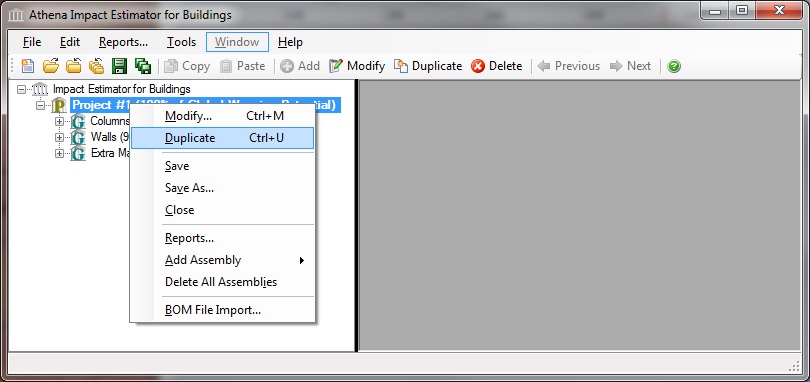
- A new Project [P] level node will be added to the Tree Control Window. By default, the new project will be named "Copy of Project #1" Lets rename the new project. Double click the new project node (alternatively you could Right click the new project node and select "Modify" from the menu). This will open the "Modify Project" dialog. Change the "Project Name" to "Project #2" then click the "OK" button.
Switch Insulation Type for Wood Stud Wall to Rockwool.
Lets change the insulation type for the double wood stud wall in Project #2 from Blown Cellulose to Rockwool Batt. To accomplish this task, you will need to insert a new envelope material for the Rockwool Batt, then delete the two entries in the Used Components list for the Blown Cellulose.
- Show the "Assembly Groups" by selecting the plus sign (+) beside the Project [P] level node for Project #2.
- Show the "Wall" assemblies by selecting the plus sign (+) beside the Assembly Group [G] level node for the "Walls" assembly group.
- Open the "Modify Custom Wall" dialog by double clicking the Assembly level node for the "Double Wood Stud Wall" assembly.
- Select the "Envelope" tab
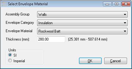
- Open the "Select Envelope Material" dialog by selecting the "Insert" button.
- Select Walls, Insulation, Rockwool Batt, 280 mm.
- Delete the Blown Cellulose envelope layers from the "Used Components" list. One at a time, select the each of the two entries for "Blown Cellulose" then click the "Remove" button.
The "Envelope" tab of the "Modify Custom Wall" dialog for the "Double Wood Stud Wall" in Project #2 will now have the following information:
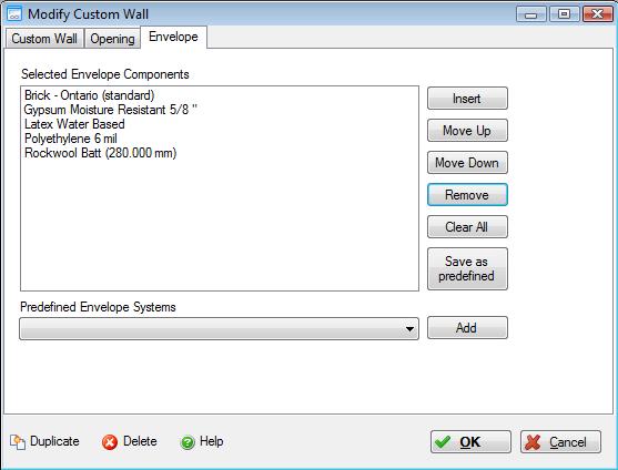
- Click the "OK" button to save the changes and close the "Modify Custom Wall" dialog.
Copy an Assembly Between Projects
Another time saving feature is the ability to copy an entire assembly, including its opening (if applicable) and envelope (if applicable) definitions to the same or another open project. In this section, you will copy the "Columns and Beams" assembly from Project #1 into Project #2.
- Show the "Assembly Groups" by selecting the plus sign (+) beside the Project [P] level node for Project #1.
- Show the "Columns and Beams " assemblies by selecting the plus sign (+) beside the Assembly Group [G] level node for the "Columns and Beams " assembly group.
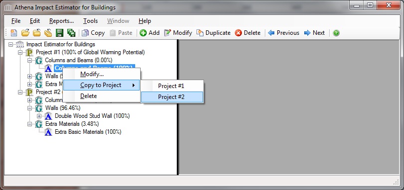
- Right click the Assembly [A] level node for the "Columns and Beams" assembly, select "Copy to Project", then select "Project #2". Alternatively, you could have selected the "Columns and Beams" assembly node, picked the "Copy" toolbar button, selected the "Project #2" project node, then picked the "Paste" toolbar button.
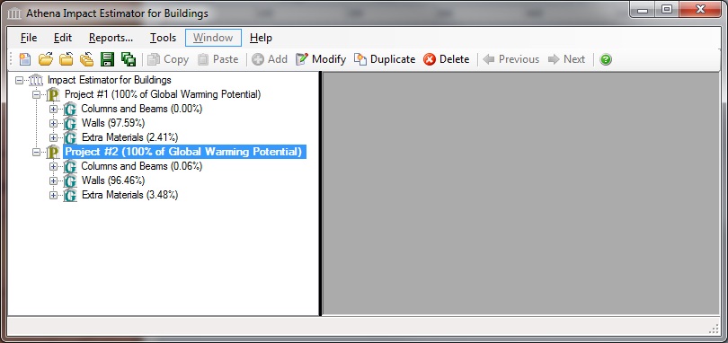
The "Tree Control Window" will now contain nodes for both projects and all of their assembly groups and assemblies.
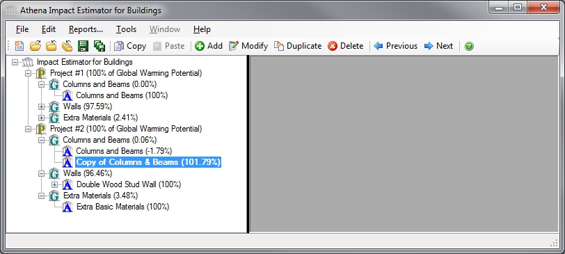
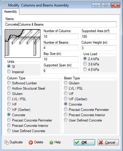
- Let's rename the new copied assembly. Double click the Assembly [A] level node for the "Copy of Columns and Beams" assembly. Change the "Assembly Name" to "Concrete Columns & Beams", change both the "Column Type" and "Beam Type" to "Concrete".
- Save Project #2. Select the "Project #2" node, then select the "Save" button from the toolbar. Alternatively, you could Right click the Project [P] level node and select the "Save" menu option, or select "Save" from the "File" menu.
Generate Project Results
For the purposes of this tutorial and so that you can see the differences between the Bill of Materials for the two projects, we will generate the "Bill of Materials" reports.
Select the Project [P] level node for "Project #2", right click and select "Reports" to open the "Reports" dialog. Alternatively, after selecting the "Project #1" Project node in the tree, you could have selected "Reports" from the main menu. See the "Reports Menu" help file for more information.
- Click the "Bill of Materials" button to generate the Bill of Materials for the project.
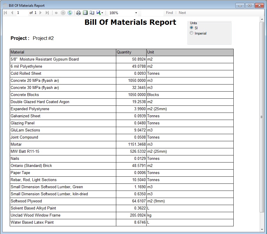
Take a moment to compare the "Bill of Materials" reports for the two projects. If you are interested, you can export each report to Excel and do even more extensive comparison and analysis there.
COMPARISON REPORTS
Generate Comparison Reports (Fossil Fuel Consumption, GWP)
Accommodating up to five comparisons at once, the Estimator allows users to change the design, substitute materials, and make side-by-side comparisons for any one or all of the environmental impact indicators. Or compare the new building design to one you did last year. You can also compare similar projects with different floor areas on a unit floor area basis. The Estimator can perform as many as five project comparisons at a time.
From a reporting perspective, all Impact Estimator results are compiled and accessed at the project level. So if you are interested in comparing two or more assemblies, rather than complete designs, you must input each assembly you want to compare as an individual project. To properly use the compare utility you need to have two or more Projects opened. See the "Reports Menu" and "Generate Reports - Multi-Project Comparison Graphs" help files for more information. If you have been following along with the tutorial thus far, you presently have "Project #1" and "Project #2" open.
To compare the two projects, do the following:
- Right click one of the Project nodes. Alternatively, you can also start by right clicking one of the Project Nodes or by selecting the "Reports" menu item from the "Main Menu".
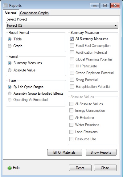
- Select "Reports" from the "Project" menu. The "Reports" dialog will open to the "General" tab. Click on the "Comparison Graphs" tab.
- Select the checkboxes for "Project #1" and "Project #2" in the list of open projects under the "Select Project(s)" label. Note: For each project that you wish to compare, double-click on the corresponding entry in the "Selected Project" list.
- From the list of "LCA Measures", select "Fossil Fuel Consumption" and "Global Warming Potential".
- Select the "Absolute Value" for the report results "Format". Later if you wish, you can use one of the selected projects as a baseline, you can pick it from the "Project Baseline" selection list.
- Select "Life Cycle Stage" for the report "Type".
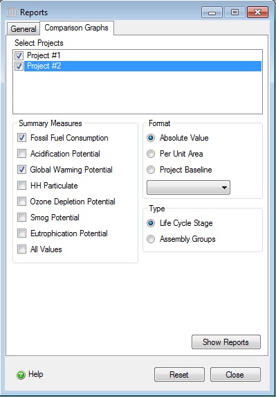
- Click the "Show Reports" button.
SAMPLE PROJECTS
Open the Sample Case Study Project Files
By now you should be familiar with the basic operations of the Impact Estimator. You are now ready to begin entering a new project of your choice or you may choose to open one of our sample case study files and augment it at your discretion. There are a number of sample case study project files included with the initial installation of the Impact Estimator for Buildings 4.1, including at least the following:
- Concrete Office Building
- R2000 House Design
- Steel Office Building
- Condo & Condo Reference
- High Bay Retail & High Bay Retail Reference
- Tutorial Project #1
- Tutorial Project #2
Both the Concrete and Steel Office Building case studies have only the structure defined, so you can immediately begin to insert envelope materials and window systems. To make it easier for you to check out some of the other reporting capabilities of the application, we have also included the R2000 house file. It is a more complete case study with the envelope and windows defined plus it also has the annual operating energy values included.
The Sample Project files are located on your hard drive in the following folder:
C:\Documents and Settings\USERNAME\My Documents\Athena\Sample Projects (Windows XP)
C:\Users\USERNAME\Documents\Athena\Sample Projects (Windows Vista or Windows 7)
ENJOY!