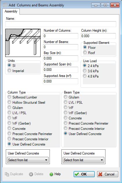
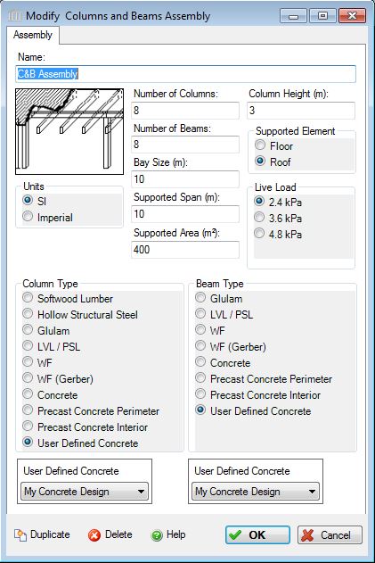
Add or Modify a Columns and Beams Assembly
 |
 |
 |
 |
As primary vertical and horizontal structural components, columns and beams are typically combined with secondary horizontal deck assemblies from the Floors and Roofs component group.
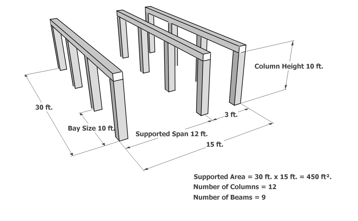
The required inputs for each of the column and beam assemblies are similar. The numbers of columns and beams define the configuration of structural bays within the building as follows. (see Figure 1)
- Columns
- Columns are counted in the direction of the main beam span. Alternatively, you can use foundational walls in place of the end columns for each row.
Beams- Beams are the number of supported structural spans. The length of each beam is the "Bay SIze"
Figure 1 - A typical Column and Beam System, used to support a floor or roof assembly.
This dialog can be used to:
- define and add a new "columns and beams" (hybrid solution) assembly to a project, or
- modify or view the information for a "columns and beams" assembly in a project
This assembly take-off allows users to combine different material columns and beams in a structural column and beam system.
See the difference between "Columns & Beams" Assembly Inputs for Version 4 versus Version 3 to see two methods for calculating the number of columns and beams.
User Defined Concrete Mix Design Note:
When "User Defined" is selected from the "Concrete" options, the "Concrete Flyash" list is disabled and a selection box listing all of the entries in the "User Defined Concrete Mix Design Library" is enabled. In order to edit the "User Defined Concrete Mix Design Library", you will need to launch the "User Defined Concrete Mix Design Library" dialog from the "Tools" menu.
Wide Flange (WF) Design Note:
As of v5.0 (July 2014), the structural calculations for WF steel beams (not columns) have been modified, depending on whether the assembly is supporting a Floor or Roof assembly. Therefore, the user must now specify what type of assembly the columns and beams are supporting. In addition, when WF beams are selected to support a roof assembly, and additional Live Load choice of 1.0 kPa (20psf) is available. Also, there is a distinction based on the building type (chosen in the modify project dialog box). If the building type is Industrial, there will be substantial differences in the material quantities calculated for Roof assemblies, and some slight differences (sometimes 0) in Floor assemblies, compared to all the other building types.
Also, there was an error detected in the July 2014 release, which didn't allow users to input a supported span greater that 12m (40ft). This was corrected and the structural calculations were adjusted accordingly for the January 2015 release. Any projects created in previous versions should load properly, but you can expect some different results in the Bill of Materials for Wide Flange Sections.
There is no longer any difference between WF and WF Gerber column or beam calculations, so WF Gerber has been removed as an option. Any projects created in previous versions will have WF Gerber automatically reassigned to WF when the project is loaded.
Seismic Note:
Seismic adjustments include extra steel on HSS and WF columns.
Field Descriptions:
(see Figure 1)- Name:
- Enter a name for this assembly. All assemblies within a project must be uniquely named within each assembly group. Names maybe alphanumeric (e.g., floor 1).
Units:- Here you can set the units of measure as either "SI" or "Imperial". Changing the default units here affects only the current assembly but will not override the Default Units of Measure nor the Units of Measure settings for open projects or any other assemblies within open projects.
Number of Columns:- Enter the total number of columns.
- Enter the number of columns per beam. Typically, the number of Columns should approximate the total length of the building when multiplied by the Bay Size (No. of Columns x Bay Size = Building Length). Alternatively, you can use foundational walls in place of the end columns for each row which yields (2 x Foundation Wall Thickness + No. of Columns x Bay Size = Building Length)
Number of Beams:- Enter the total number of beams.
- Enter the number of beams. The number of beams is equal to the number of supported spans. Typically, the number of beams should approximate the width of the building when multiplied by the Supported Span (No. of Beams x Supported Span = Building Width)
Bay Size:- Enter the bay size (main beam span) that most accurately reflects your design intentions. See also "Number of Columns" field above. The bay size is is constrained to be between 3.05 m and 12.2 m for all live loads and beam types.
Supported Span:- Enter the supported span (distnce between parallel rows of beams) that most accurately reflects your design intentions.
See also "Number of Beams" field above.
Design span ranges are:- Glulam Beam : 0.0m < span <= 13.7m for all live loads.
- LVL/PSL Beam : 0.0m < span <= 13.7m for all live loads.
- Wide Flange Beam : 0.0m < span <= 21.3m for all live loads.
- Wide Flange Gerber Beam : 0.0m < span <= 21.3m for all live loads.
- Concrete Beam : 2.0m < span <= 21.3m for all live loads.
- Precast Concrete Perimeter Beam : 0.0m < span <= 21.3m for all live loads.
- Precast Concrete Interior Beam : 0.0m < span <= 21.3m for all live loads.
Supported Area:- Enter the total area directly supported by the columns and beams.
Column Height:- Enter the column height (previously labelled floor-to-floor height)
Supported Element:- Enter the assembly type that this Column and Beam assembly will support.
Live Load:-
Click a radio button to select the live load to be carried by this column and beam assembly system. 2.4kPa represents a typical roof load for a typical office / residential occupancy condition (above the first floor while 3.6 kPa represents a typical mechanical/service room loading and 4.8 kPa would be indicative of heavier floor loads such as assembly areas, balconies/mezzanines, corridors, lobbies/exit areas and storage areas.
The user may click one of the following live loads to be included in the assembly.
- 1.0 kPa (20 psf) - available only for WF Beams, supporting a Roof Element
- 2.4 kPa (50 psf)
- 3.6 kPa (75 psf)
- 4.8 kPa (100 psf)
Column Type:-
The user may click one of the following column types to be included in the assembly.
- Softwood Lumber
- Hollow Structural Steel (HSS)
- Glulam
- LVL/PSL (Laminated Veneer Lumber/Parallel Strand Lumber)
- WF (Wide Flange Steel)
- WF Gerber (Wide Flange Steel)
- Concrete
- Precast Concrete Perimeter
- Precast Concrete Interior
- User Defined Concrete
Column Type Details
Column Type Details Softwood Lumber Based on 140mm x140mm wood columns for 2.4 and 3.6 kPa live loads and 191mm x 191mm columns for 4.8 kPa live loads. HSS Column Based on 125 x 125 x 6mm thick HSS columns for 2.4 and 3.6 kPa loads and 200mm x 200mm x 6mm columns for 4.8kPa loads. Seismic adjustments will add extra steel to HSS columns. LVL/PSL Column Based on 121mm x121mm wood columns for 2.4 and 3.6 kPa live loads and 165mm x 165mm columns for 4.8 kPa live loads. WF Column Based on Wide Flange sections of 25.3 kg/m for 2.4 and 3.6 kPa live loads and 40.5 kg/m sections for 4.8 kPa live loads. Seismic adjustments will add extra steel to HSS columns. Concrete Column Based on manufacturer guidelines, Canadian design codes and experience in typical applications of this system, 30 MPA or 4000 psi concrete. Precast Concrete Perimeter Column Based on manufacturer guidelines, Canadian design codes and experience in typical applications of this system
Although typically, precast floor/roof assemblies do not exceed 15m (50ft), supported spans up to 21.3m (70ft) are allowed for precast columns in case other floor/roof systems are used on precast columns.
Precast Concrete Interior Column Based on manufacturer guidelines, Canadian design codes and experience in typical applications of this system
Although typically, precast floor/roof assemblies do not exceed 15m (50ft), supported spans up to 21.3m (70ft) are allowed for precast columns in case other floor/roof systems are used on precast columns.
User Defined Concrete A user defined concrete mix design
Beam Type:-
The user may click one of the following beam types to be included in the assembly.
- Glulam
- LVL/PSL
- WF
- WF (Gerber)
- Concrete
- Precast Concrete Perimeter
- Precast Concrete Interior
- User Defined Concrete
Beam Type Details
Beam Type Details Glulam Beam - Glue laminated beams, based on 24F grade beams.
- Steel beam to column and column shoe connectors are included (modeled as HSS steel)
LVL/PSL Beam - Laminated veneer lumber beams ,based on 1.8E Fir Microlam beams.
- Steel beam to column and column shoe connectors are included (modeled as HSS steel)
WF Beam - Wide Flange steel beams. This primary structural assembly will typically be combined with the Open Web Steel Joist (OWSJ) assemblies from the Floors and Roofs component group.
- Beams are sized based on load and span conditions.
- The program makes an allowance for additional material (Screws, Nuts and Bolts) at column and beam connections.
- Quantities will depend on the Supported Element Type
Concrete Beam - Assembly is based on manufacturer guidelines, Canadian design codes and experience in typical applications of this system
- The Bay Area (Bay Size X Supported Span) must be greater than 20.0m2 for all loads. If the entered Bay Area is less than the minimum value, a minimum Bay Area of 20.0m2 is used for calculating material requirements. The material requirements are then factored by multiplying the material requirements quantities by the entered Bay Area divided by the minimum Bay Area.
Precast Concrete Perimeter Beam - Assembly is based on manufacturer guidelines, Canadian design codes and experience in typical applications of this system
- Although typically, precast floor/roof assemblies do not exceed 15m (50ft), supported spans up to 21.3m (70ft) are allowed for precast beams in case other floor/roof systems are used on precast beams.
Precast Concrete Interior Beam - Assembly is based on manufacturer guidelines, Canadian design codes and experience in typical applications of this system
- Although typically, precast floor/roof assemblies do not exceed 15m (50ft), supported spans up to 21.3m (70ft) are allowed for precast beams in case other floor/roof systems are used on precast beams.
User Defined Concrete A user defined concrete mix design
Duplicate Button- Click the "Duplicate" button to create an exact duplicate of the current assembly. The duplicate assembly will be added to the current project. This button is only available when editing or viewing an assembly that has already been saved in the current project.
Delete Button- Click the "Delete" button to delete the current assembly from the current project. This button is only available when editing or viewing an assembly that has already been saved in the current project.
Help Button:- Click the "Help" button to open the Help pop-up window.
OK Button- Click the "OK" button to accept and save the current assembly settings and close this dialog.
Cancel Button- Click the "Cancel" button to discard the current assembly settings and close this dialog
Glossary of Terms
- HSS
- Hollow Structural Steel
LVL- Laminated Veneer Lumber
PSL- Parallel Strand Lumber
WF- Wide Flange Steel
Difference between "Columns & Beams" Assembly Inputs for Version 4 versus Version 3
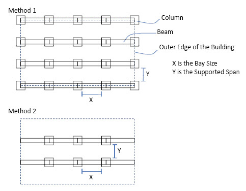 |
In version 3 users were only able to use Method 1 to calculate the inputs for "Columns and Beams", making the inputs a total of 20 "Columns" and 16 "Beams". However, in version 4 the user has the ability to choose between Method 1 and Method 2 when calculating inputs for "Columns and Beams". In Method 2 the "Outer Edge of the Building" represents the first and last "Column" in each row and column, as well as any overlapping "Beams". Therefore, using Method 2 would result in inputs of 6 "Columns" and 8 "Beams". |