Add or Modify a Metal Building System - Wall Assembly
 |
 |
FOR DEMONSTRATION PURPOSES ONLY
The prototype version of Pre-engineered metal wall systems is presented for demonstration purposes only.
A more generalized system definition is planned to be available in early 2012.
This dialog can be used to:
- Define and add a new "Metal Building System - Wall" sub-assembly to a "Custom Wall" assembly in the project, or
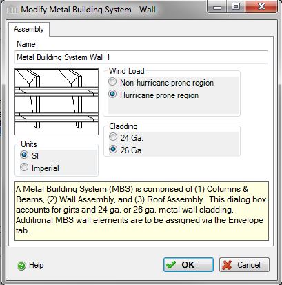
- Modify or view "Metal Building System - Wall" sub-assembly in the project.
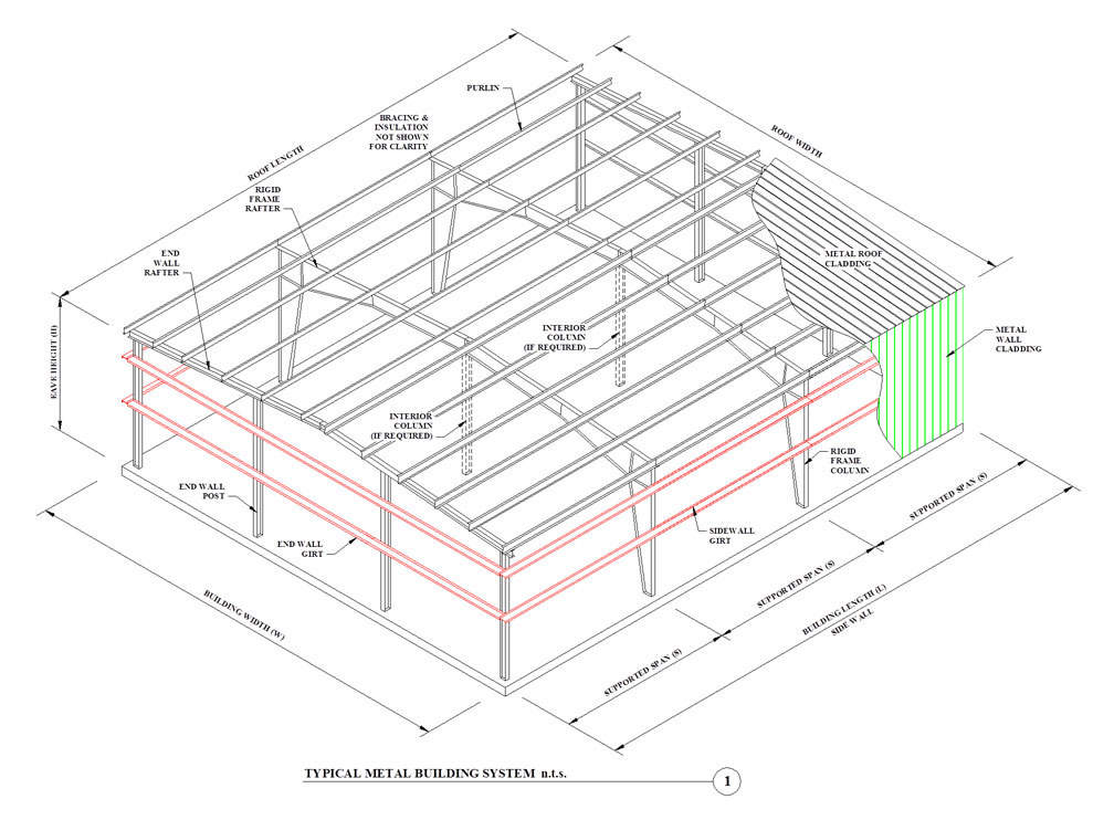
A metal building system is an integrated set of components and assemblies, including but not limited to frames that are built-up structural steel members, secondary members that are cold-formed steel or steel joists, and cladding components, specifically designed to support and transfer loads and provide a complete or partial building shell. These components and assemblies are manufactured in a manner that permits plant and/or field inspection prior to assembly or erection. [Ref. Metal Building Systems Manual, MBMA 2012]. Most metal buildings are no longer "pre-engineered" or selected from a catalog of standard designs. Metal building systems are custom designed buildings based on applicable building codes, loading conditions, and serviceability requirements. The focus of this software is not to design a metal building as described above, but rather focused on conceptual design. This conceptual design will be sufficient enough to obtain a bill of material from the software in order to perform environmental impact calculations.
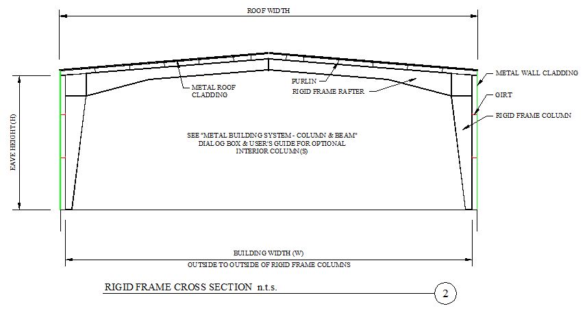
A typical metal building system structure is illustrated below, along with a cross section. The "Metal Building Systems - Wall" dialog box accounts for the wall girts (as shown in red below) and 24 ga or 26 ga metal wall cladding. Additional tabs (i.e. Openings & Envelope) are available within the dialog box to account for door and window openings (not shown below) and for wall elements.
Other main components of a Metal Building Systems may be derived from the following dialog boxes:
| Description / Assumptions / Limits | Required inputs |
|---|---|
Metal Building System - Wall
|
|
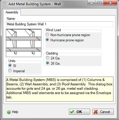
Required Inputs:
- Name:
- Enter a name for this assembly. All assemblies within a project must be uniquely named within each assembly group. Names maybe alphanumeric (e.g., MBS Wall 1, MBS Wall 2, etc.).
Units:- Here you can set the units of measure as either "SI" or "Imperial". Changing the default units here affects only the current assembly but will not override the Default Units of Measure nor the Units of Measure settings for open projects or any other assemblies within open projects.
Wind Load:- This software utilizes data files and look up values for wind velocity pressures commonly used within the National Building Code of Canada (i.e. Hourly Wind Pressures, kPa). Since this tool will be used for locations within Canada and the United States, we have provided two options simplified as it is helpful to equate this to Hurricane prone region or Non-hurricane prone regions.
Hurricane prone region:- Click this option for hurricane prone regions as called out by ASCE 7 wind speed maps or Canadian regions with wind loads ranging from 0.5 kPa (10.4 psf) to 0.6 kPa (12.5 psf).
Non-hurricane prone region:- Click this option for non-hurricane prone regions as called out by ASCE 7 wind speed maps or Canadian regions with wind loads ranging from 0.3 kPa (6.3 psf) to 0.4 kPa (8.4 psf).
- Click a radio button to select the average wind load for this assembly.
- High Wind Average (0.55 kPa)
- Low Wind Average (0.35 kPa)
Standard Dialog Box Buttons:
Help Button:- Click the "Help" button to open the Help pop-up window.
OK Button- Click the "OK" button to accept and save the current assembly settings and close this dialog.
Cancel Button- Click the "Cancel" button to discard the current assembly settings and close this dialog.
Notes:
Seismic Note:- Seismic adjustments include extra steel on primary [including bracing] and secondary structural elements (such as purlins and girts).
Wall Assembly Note:- The Metal Building System Wall dialog box accounts for the secondary framing (i.e. the girt) located on the end walls and side walls, as well as 24 gauge or 26 gauge wall cladding. A girt is the horizontal structural member that is attached to sidewall or endwall columns and supports paneling. Girts may be in the shape of a cee or zee. Girts are typically 8 inches in depth and spaced vertically 8-0 (+/-) on center.
-
Cladding:- Two options common to metal building systems include 24 gauge and 26 gauge metal wall cladding. Note, additional 26 gauge corner trim and downspout material are added to the Bill of Material (BOM) report, regardless if one selects 24 gauge or 26 gauge metal wall cladding.
Wall Components Common to Metal Building Walls:- Additional wall components (i.e. insulation, vapor barrier, etc.) must be selected from the Envelope tab within the "Custom Wall" dialog box. The user may Predefine an envelope system based on the tools supplied components for various envelope categories for Gypsum Board, Insulation, Paint, and Vapor & Air Barrier. If the structure has more than one layer of as certain element, then it would need to be entered in more than once to make up the assembly.
Insulation: There are various options for the user to choose from. Materials common to metal buildings include at least one layer of faced fiber glass insulation with additional layers being unfaced. The fiber glass options contain therein are unfaced. One would need to go to the Vapor & Air Barrier category to add in the laminated vapor retarder. Enter in the uncompressed thickness of the insulation associated with the R-value chosen (this would not be the compressed insulation thickness at the framing member). Other options that are applicable to metal building walls are the continuous insulation systems (i.e. poly ) listed that can be used alone or in conjunction with the batt insulation. Lastly, mineral wool is commonly used for its insulation properties or to meet a fire code assembly listing.
Vapor & Air Barrier: There are a few options to choose from, one of which is the Polypropylene scrim kraft or PSK. PSK is commonly used with metal building insulation assemblies either laminated to the batt insulation or provided separately.
Paint: This option would be selected if the gypsum board wall was painted on the interior. Exterior products (i.e. cladding) would already account for any painting or coating conducted during the manufacturing process of the material.
Other Assembly Components::- Other available assembly components are noted in the "Custom Wall" dialog box that may coincide with a typical metal building structure. Such as Concrete Block, Cast-in Place and Tilt Up Concrete, Curtain Walls, Insulated Concrete Forms, Steel Studs, Wood Studs, and Structural Insulated Panels.
Length:- The length is inherited from the "Custom Wall" assembly to which this wall "component" sub-assembly belongs.
Height:- The height is inherited from the "Custom Wall" assembly to which this wall "component" sub-assembly belongs.
Openings:- Openings for windows and doors are not captured for this "component" sub-assembly. Rather, openings are defined within the "Openings" tab.