Add or Modify a Metal Building Systems - Columns & Beams Assembly
 |
 |
 |
 |
FOR DEMONSTRATION PURPOSES ONLY
The prototype version of Pre-engineered metal building systems is presented for demonstration purposes only.
A more generalized system definition is planned to be available in early 2012.
Pre-engineered metal building systems are most commonly single story packaged metal building systems that typically include wall assemblies, roof assemblies, columns and beams.
This dialog can be used to:
- Define and add a new "Metal Building Systems - Columns & Beams" assembly to a project, or
- Modify or view the information for a "Metal Building Systems - Columns & Beams" assembly in a project
A metal building system is an integrated set of components and assemblies, including but not limited to frames that are built-up structural steel members, secondary members that are cold-formed steel or steel joists, and cladding components, specifically designed to support and transfer loads and provide a complete or partial building shell. These components and assemblies are manufactured in a manner that permits plant and/or field inspection prior to assembly or erection. [Ref. Metal Building Systems Manual, MBMA 2012]. Most metal buildings are no longer "pre-engineered" or selected from a catalog of standard designs. Metal building systems are custom designed buildings based on applicable building codes, loading conditions, and serviceability requirements. The focus of this software is not to design a metal building as described above, but rather focused on conceptual design. This conceptual design will be sufficient enough to obtain a bill of material from the software in order to perform environmental impact calculations.
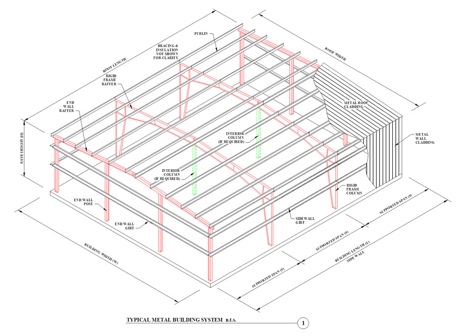
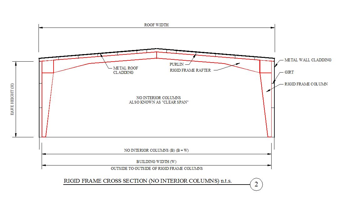
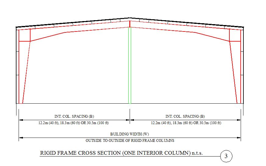
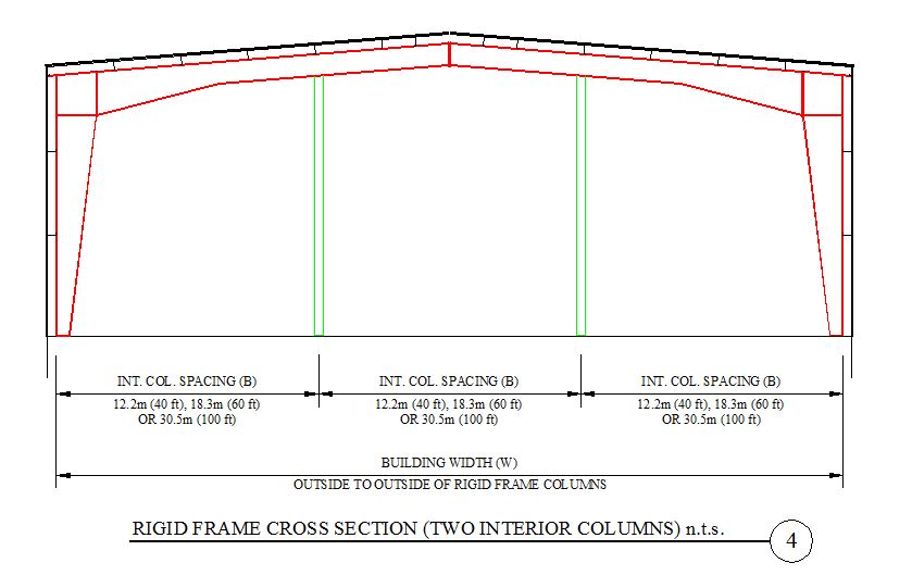
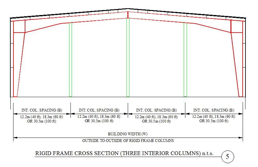
A typical metal building system structure is illustrated below, along with a cross sections. The focus of the "Metal Building Systems - Column & Beam" dialog box accounts for the rigid frame column, rigid frame rafter, end wall post, end wall rafter (as shown in red below), along with bracing not shown. The dialog box accounts for interior columns (if applicable), as illustrated in green below and via cross sections.
Other main components of a Metal Building Systems may be derived from the following dialog boxes:
Seismic Note:
Seismic adjustments include extra steel on secondary structural elements.
Dialog Box Descriptions/Descriptions:
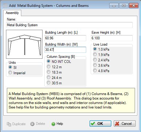
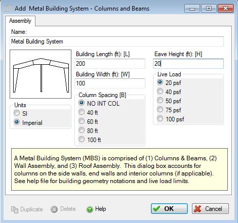
- Name:
- Enter a name for this assembly. All assemblies within a project must be uniquely named within each assembly group. Names maybe alphanumeric (e.g., MBS 1).
Units:- Here you can set the units of measure as either "SI" or "Imperial". Changing the default units here affects only the current assembly but will not override the Default Units of Measure nor the Units of Measure settings for open projects or any other assemblies within open projects.
Building Geometry:
Note the building geometry (i.e. building length, width, height, column spacing, supported span) information is to be entered into the dialog box based on best approximation. See limitations noted below. Total building length and width: The equations for unit material weight are based on a typical building measuring 200 ft x 200 ft (40,000sf).
Building Length (L):- Enter the total length of the structure. The dimension of the building measured perpendicular to the main framing from end wall to end wall (parallel to the roof purlins).
Building Width (W):- Enter the total width of the structure. The dimension of the building measured parallel to the main framing from sidewall to sidewall (perpendicular to the roof purlins). Building width must be a multiple of equal column spacing options (noted below), if the building includes interior columns supporting the rigid framing. If no interior columns, then the maximum width of the building is limited to 30.48 m (100 feet).
Eave Height (H):- The eave height is the height of the rigid frame columns at the edge of the structure side walls. The default (typical) eave height is 6.1 m (20 feet). Metal building system heights usually range between 3.05 m (10 feet) and 8.5 m (28 feet), thus the user will be limited to heights within this range.
Column Spacing (B)1:- The column spacing is defined as the distance between columns along the main rafter beam of the structure and is measured along the width of the building. Columns includes the rigid frame columns and interior columns (if applicable), as well as the end wall columns. Column Spacing is selected by the user via a radio button in the dialog box. Software supported Column Spacing include: 12.2 m (40 ft.), 18.3 m (60 ft.), 24.4 m (80 ft.), and 30.5 m (100 ft.). If there are no internal columns, the user should select "NO INT COL" and the column spacing will be equal to the building width. An interior column free metal building is known as a single-span rigid frame ranging in widths from 6.1 m (20 ft.) to over 48.8 m (160 ft.).
Supported Span (S)1:- The supported span is defined as the distance between the main rigid frame columns along the length of the structure. The most common supported span distance is 7.62 m (25 ft), however metal buildings are often designed to support spans of 18.29 m (60 ft.)or more. In the development of the equations used in this software, the supported span was set to 7.62 m (25 ft.). For situations where the supported span differs significantly, the user may prefer to enter their primary and secondary frame quantities separately using the "Extra Basic Materials" input capability in the software.
Load Application:- This software does not account for all loads that a metal building systems designer would use to design the structure to meet the requirements of the building codes. Since this software tool is more applicable to conceptual design, it is important to clarify what does the term Live Load entail. The Live Load options (as described below) only applies to the total controlling applied roof gravity load, including snow &/or collateral load. Wind load is not an input parameter. Seismic loads have been addressed via extra steel for primary and secondary structural elements for high seismic areas covered by the software.
Live Load:- Click a radio button to select the live load to be carried by the metal building system column and beam assembly.
The user may click one of the following live loads to be included in the assembly:- 1.0 kPa (20 psf)
- 1.9 kPa (40 psf)
- 2.4 kPa (50 psf)
- 3.6 kPa (75 psf)
- 4.8 kPa (100 psf)
Standard Dialog Box Buttons:
Duplicate Button- Click the "Duplicate" button to create an exact duplicate of the current assembly. The duplicate assembly will be added to the current project. This button is only available when editing or viewing an assembly that has already been saved in the current project.
Delete Button- Click the "Delete" button to delete the current assembly from the current project. This button is only available when editing or viewing an assembly that has already been saved in the current project.
Help Button:- Click the "Help" button to open the Help pop-up window.
OK Button- Click the "OK" button to accept and save the current assembly settings and close this dialog.
Cancel Button- Click the "Cancel" button to discard the current assembly settings and close this dialog.
Notes:
Seismic Note:- Seismic adjustments include extra steel on primary [including bracing] and secondary structural elements.