Add or Modify a Metal Building System - Roof Assembly
 |
 |
 |
 |
FOR DEMONSTRATION PURPOSES ONLY
The prototype version of Pre-engineered metal roof systems is presented for demonstration purposes only.
A more generalized system definition is planned to be available in early 2012.
This dialog can be used to:
- Define and add a new "Metal Building System - Roof" assembly to a project, or
- Modify or view a "Metal Building System - Roof" assembly that has been added to a project.
- Define an envelope for this assembly.
| Description / Assumptions / Limits | Required inputs |
|---|---|
Metal Buildnig System - Roof
|
|
A metal building system is an integrated set of components and assemblies, including but not limited to frames that are built-up structural steel members, secondary members that are cold-formed steel or steel joists, and cladding components, specifically designed to support and transfer loads and provide a complete or partial building shell. These components and assemblies are manufactured in a manner that permits plant and/or field inspection prior to assembly or erection. [Ref. Metal Building Systems Manual, MBMA 2012]. Most metal buildings are no longer "pre-engineered" or selected from a catalog of standard designs. Metal building systems are custom designed buildings based on applicable building codes, loading conditions, and serviceability requirements. The focus of this software is not to design a metal building as described above, but rather focused on conceptual design. This conceptual design will be sufficient enough to obtain a bill of material from the software in order to perform environmental impact calculations.
A typical metal building system structure is illustrated below, along with a cross section. The focus of the initial "Metal Building Systems - Roof" dialog box accounts for the roof purlins and 24 ga or 26 ga metal roof cladding (as shown in red below). Additional tabs are available within the Wall dialog box to account for "Envelope " elements.
Other main components of a Metal Building Systems may be derived from the following dialog boxes:
Required Inputs:
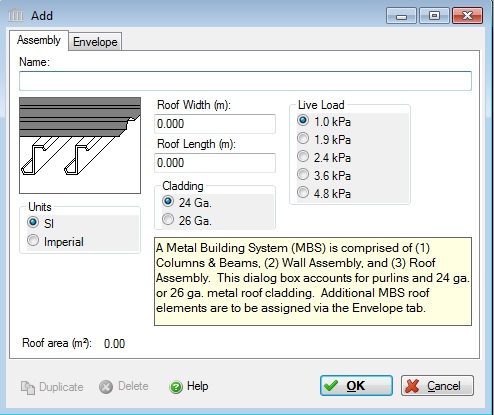
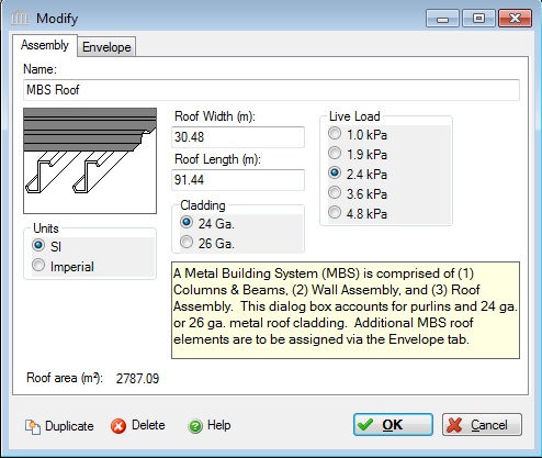
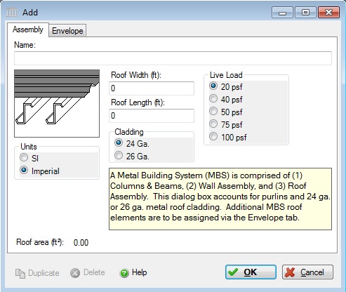
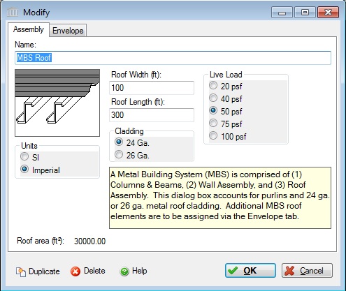
- Name:
- Enter a name for this assembly. All assemblies within a project must be uniquely named within each assembly group. Names maybe alphanumeric (e.g., MBS Roof1, MBS Roof 2, etc.), if you have more than one roof type utilized on the structure.
Units:- Here you can set the units of measure as either "SI" or "Imperial". Changing the default units here affects only the current assembly but will not override the Default Units of Measure nor the Units of Measure settings for open projects or any other assemblies within open projects.
Roof Width:- Enter the roof width in m or ft. Enter the total width of the structure. The dimension of the building measured parallel to the main framing from sidewall to sidewall (perpendicular to the roof purlins).
Roof Length:- Enter the roof length in m or ft. Enter the total length of the structure. The dimension of the building measured perpendicular to the main framing from end wall to end wall (parallel to the roof purlins).
Load Application:- This software does not account for all loads that a metal building systems designer would use to design the structure to meet the requirements of the building codes. Since this software tool is more applicable to conceptual design, it is important to clarify what does the term Live Load entail. The Live Load options (as described below) only applies to the total controlling applied roof gravity load, including snow &/or collateral load. Wind load is not an input parameter. Seismic loads have been addressed via extra steel for primary and secondary structural elements for high seismic areas covered by the software.
Live Load: Click a radio button to select the live load to be carried by the metal building system roof assembly.
The user may click one of the following live loads to be included in the assembly:- 1.0 kPa (20 psf)
- 1.9 kPa (40 psf)
- 2.4 kPa (50 psf)
- 3.6 kPa (75 psf)
- 4.8 kPa (100 psf)
Roof Area (m2 or ft2) Note:- As a user friendly check, the total roof area calculated by the application (as per the users input) is reported in the bottom left hand corner of the dialog box.
Standard Dialog Box Buttons:
Duplicate Button- Click the "Duplicate" button to create an exact duplicate of the current assembly. The duplicate assembly will be added to the current project. This button is only available when editing or viewing an assembly that has already been saved in the current project
Delete Button- Click the "Delete" button to delete the current assembly from the current project. This button is only available when editing or viewing an assembly that has already been saved in the current project.
Help Button:- Click the "Help" button to open the Help pop-up window.
OK Button- Click the "OK" button to accept and save the current assembly settings and close this dialog.
Cancel Button- Click the "Cancel" button to discard the current assembly settings and close this dialog.
Notes:
Seismic Note:- Seismic adjustments include extra steel on primary [including bracing] and secondary structural elements (such as purlins and girts).
Roof Assembly Note:- The “Metal Building System – Roof” dialog box accounts for the secondary framing (i.e., purlins) that is being attached to the rigid frame rafters and end wall rafters (i.e. beams), as wellas 24 gauge and 26 gauge roof cladding. A purlin is the horizontal structural member that supports the roof covering. Purlins may be in the shape of a “cee” or “zee”. Purlins are typically 8 inches to 12 inches in depth and spaced 5’-0” (+/-) on center on average.
-
Cladding:- Two options common to metal buildings include 24 gauge and 26 gauge metal roof cladding. Note, additional 26 gauge perimeter roof line and ridge trim are added to the Bill of Material (BOM) report, regardless if one selects 24 gauge or 26 gauge metal roof cladding.
Additional Roof Components need to make up a Metal Building Roof Assembly:- Additional roof components (i.e. insulation, vapor barrier, etc.) must be selected from the “Envelope” tab within the “"Custom Wall" ” dialog box. The user may “Predefine” a roof envelope system based on the tool’s supplied components for various envelope categories.
Common envelope materials for metal building would fall under the following categories: Metal Roof System, Insulation, Vapor & Air Barrier, and Gypsum Board. If the structure has more than one layer of as certain element, then it would need to be entered in more than one time to make up the assembly.
Insulation There are various options for the user to choose from. Materials common to metal buildings include at least one layer of faced fiber glass insulation with additional layers being unfaced. The fiber glass options contain therein are unfaced. One would need to go to the Vapor & Air Barrier category to add in the laminated vapor retarder. Enter in the uncompressed thickness of the insulation associated with the R-value chosen (this would not be the compressed insulation thickness at the framing member). Other options that are applicable to metal building walls are the continuous insulation systems (i.e. poly…) listed that can be used alone or in conjunction with the batt insulation. Lastly, mineral wool is commonly used for its insulation properties or to meet a fire code assembly listing.
Vapor & Air Barrier: There are a few options to choose from. Polypropylene scrim kraft or PSK is commonly used with metal building insulation assemblies either laminated to the batt insulation or provided separately.
Gypsum Board: This is a common material used on a metal building wall in order to meet fire codes and/or finish out the interior of the building for cosmetic use. Various options are provided within the tool. Multiple layers of gypsum board may need to be accounted for.
Note the software does not account for roof openings, such as skylights, roof vents, etc.