Add or Modify a Cross Laminated Timber Floor
 |
 |
 |
 |
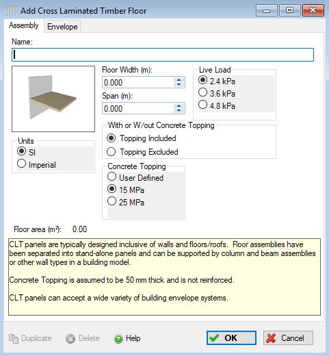
This dialog can be used to:
- define and add a "cross laminated timber floor " assembly to a project, or
- modify or view "cross laminated timber floor" assembly that has been added to a project.
- define an envelope for this assembly.
| Description / Assumptions / Limits | Required inputs |
|---|---|
Cross Laminated Timber (CLT) floor
|
|
Benchmark Concretes (selected with radio buttons) Note:
The Canadian and American ready mix associations, CRMCA and NRMCA, have published EPDs with multiple mix designs, those mix designs are available to import into users User Defined Concrete Mix Design Libraries, for instructions on how to do this download the PDF file at File>Bulk Product Projects.
Two benchmark designs are available in each concrete assembly as radio button choices ranging from 15 MPa (2500 psi) and 25 MPa (3000 psi). When a user chooses one of these benchmark mixes for an assembly for project locations in Canada, the CRMCA mix will be added to the bill of materials, and for projects in US locations, the NRMCA mix will be added. The NRMCA EPD included a 2500 psi (15 MPa) benchmark mix, but the CRMCAs EPD did not include a 15 MPa mix. Therefore, the mix design for Concrete Benchmark CAN 15 MPa is in fact the mix design from the NRMCA EPD and cannot be found in the CRMCA EPD.
Remember that these mix designs only define the amounts of each individual material in each mix, the LCA effects for each of those materials are calculated with material data according to the project location. In other words, the Canadian 15 MPa concrete copies an NRMCA mix design, but uses Canadian data for Portland cement, aggregates, etc.
There are six NRMCA benchmark mixes and eight CRMCA benchmarks in the database. The NRMCA 4000, 5000, 6000 and 8000 psi bencnmarks and the CRMCA 30, 35, 45, 50, 55 and 60 MPa benchmarks are not available to choose from in the assembly dialogs, but they are included in the database. If you wish to use one of these benchmarks in your assembly, you can choose them as user defined products, but in order to do that, you must create them as user defined products. To do this, go to Tools> User Defined Concrete Mix Design Library, check the Include Database Products box at the top of the form, and the database products will appear in grey. Click the product you want, then click Duplicate, and a copy will be created. We recommend you rename this duplicate so that you can distinguish it from the database version. This is now a User Defined copy of the database mix and will be available in the User Defined drop down box of each concrete assembly form. All mixes, database and user defined are available in Extra Basic Materials.
The CRMCA EPD report is available at https://www.crmca.ca/s/CRMCA-EPD-20170317.pdf
The NRMCA EPD report is available at https://www.nrmca.org/sustainability/EPDProgram/Index.asp#IndustryWideEPD
User Defined Concrete Mix Design Note:
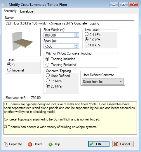
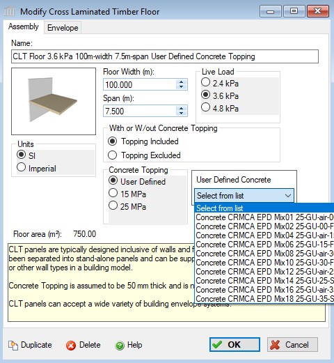
When "User Defined" is selected from the "Concrete" options, the "Concrete Flyash" list is disabled and a selection box listing all of the entries in the "User Defined Concrete Mix Design Library" is enabled. In order to edit the "User Defined Concrete Mix Design Library", you will need to launch the "User Defined Concrete Mix Design Library" dialog from the "Tools" menu.
Seismic Note:
Since the CLT panels are very rigid elements and resist lateral loads well, their size and mass are not likely to be affected by the seismic loading. Therefore, there are no seismic adjustments for the panels.
Connections:
- The floor panel bears directly on the wall and proprietary long screws are fastened through its entire thickness into the wall. Other support edge connections are added to CLT wall assemblies.
On-site Waste:
CLT produces very little waste on site. Panels are custom manufactured in the factory specific for each application on each project. Door and window openings are typically made in the factory, although occasionally some openings are made on site should the opening present a risk of panel damage when lifting. On occasion, panels are sold in bulk and cut to length on site, but this is an uncommon practice. Fastener materials are manufactured off site, although we would expect a small amount of fastener waste due to over-supply or damaged fastener material. Overall, we believe a factor of 1% waste should be carried for CLT floor panels and 3% for the fasteners (which is the default construction waste factor in the tool for Screws, Nuts and Bolts) to account for the small amount of waste that could be present. Given the small amount of waste, we would expect it would end up in landfill, although on some projects it may be recycled.
Maintenance and Repair:
In the life of a building, there is no typical repair or maintenance items associated with CLT. Envelope materials that are added to the assembly will be replaced per their replacement cycle.
End of Life:
CLT based buildings are new to the market, so no information is available on CLT would typically perform for the life of the building, after which we would expect they would be disposed of at clean fill dump sites or landfills. In some cases, they could be re-used or used as a fuel source for energy production, or potentially ground into mulch and recycled. Given the lack of relevant information, we treat CLT the same as glulam with respect to the type of disposal at end-of-life.
Envelope Considerations:
CLT panels can accept a wide variety of building envelope systems.
Cautionary Note:
- If you want to suspend this assembly on CLT walls, you will need to use the Cross Laminated Timber Wall assembly.
- If you want to suspend this assembly on columns, you will also need to use the Columns and Beams assembly.
Cautionary Note:
The flyash concentration levels as provided should be treated as indicators only of employing more or less flyash in a typical mix. The results for different regions of N. America may be quite different and local conditions, availability and design mixes should be consulted.
Field Descriptions:
- Name:
- Enter a name for this assembly. All assemblies within a project must be uniquely named within each assembly group. Names maybe alphanumeric (e.g., floor 1).
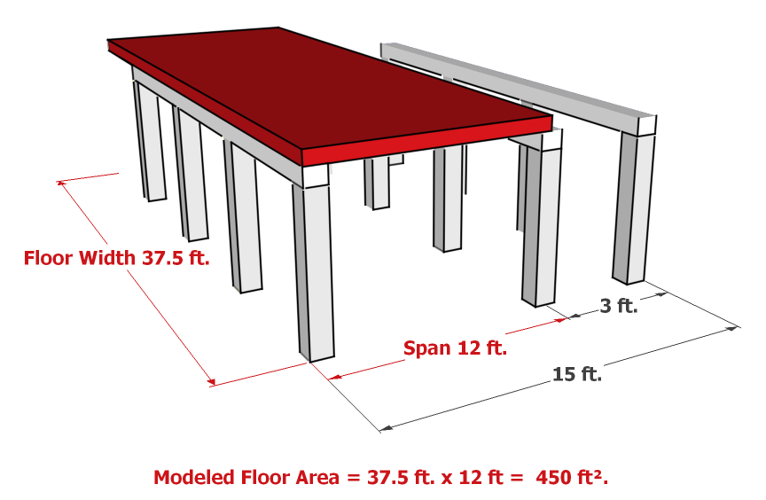
Floor Width:- Enter the floor width in m or ft. The floor width is calculated as follows: Total Floor Area / Supported Span = Floor Width. The user must enter this floor width, in m or ft.
Span:- The span determines the thickness of the floor needed. If a rectangular floor is supported on all four sides, then typically the span would be the short side of that rectangle (within the constraints above)in m or ft. If the floor is supported on two sides, then the span should be the maximum distance between beams (within the constraints above) The user should enter a span and adjust the Floor Width in order to achieve the desired Floor Area.
*For either situation, see Important Note below regarding Span and Width entries.
Concrete:- Click a radio button to select the desired concrete strength class.
- Concrete 20 MPa (m3) or 3000 psi (cubic yards) with flyash concentrations of average (9%) or 25% or 35% cement replacement.
- Concrete 30 MPa (m3) or 4000 psi (cubic yards) with flyash concentrations of average (9%) or 25% or 35% cement replacement.
- Concrete 60 MPa (m3) or 9000 psi (cubic yards) with silica fume concentrations of 10%. No flyash (silica fume) variations are provided for this design mix.
- User Defined Concrete Mix Design.
Concrete Flyash %:- Click a radio button to select the percentage concentration of flyash cement replacement to be used in this assembly - see the cautionary note above.:
- average (9%)
- 25%
- 35%
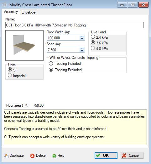
Live Load:- Click a radio button to select the live load to be carried by this floor assembly.
- 2.4 kPa (50 psf) represents a typical roof load for a typical office / residential occupancy condition (above the first floor)
- 3.6 kPa (75 psf) represents a typical mechanical/service room loading
- 4.8 kPa (100 psf) would be indicative of heavier floor loads such as assembly areas, balconies/mezzanines, corridors, lobbies/exit areas and storage areas.
Units:- Here you can set the units of measure as either "SI" or "Imperial". Changing the default units here affects only the current assembly but will not override the Default Units of Measure nor the Units of Measure settings for open projects or any other assemblies within open projects.
Floor Area (m2 or ft2) Note:- As a user friendly check, the total floor area calculated by the application (as per the users input) is reported in the bottom left hand corner of the dialog box.
Duplicate Button- Click the "Duplicate" button to create an exact duplicate of the current assembly. The duplicate assembly will be added to the current project. This button is only available when editing or viewing an assembly that has already been saved in the current project.
Delete Button- Click the "Delete" button to delete the current assembly from the current project. This button is only available when editing or viewing an assembly that has already been saved in the current project.
Help Button:- Click the "Help" button to open the Help pop-up window.
OK Button- Click the "OK" button to accept and save the current assembly settings and close this dialog.
Cancel Button- Click the "Cancel" button to discard the current assembly settings and close this dialog.
Important Note:
With Floor assemblies, the critical input is the Span. This should be the maximum span that the assembly will be subjected to, and it will determine the size of the assembly needed. For example, in a CLT floor, the span will determine how thick the floor needs to be. The Width is used to account for the total area of the assembly, and may not be the actual width of the assembly. The following Figure 1 shows an actual floor as designed (the yellow floor assembly), and Figure 2 shows how that assembly must be modelled in Impact Estimator (the red equivalent assembly). Notice that the equivalent assembly's width has been changed so the total area of the assembly stays the same, and the span is entered to reflect the maximum span (between the first two rows of beams).
Figure 1
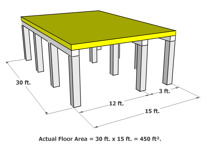
Figure 2