Add or Modify a Cross Laminated Timber Wall Assembly
 |
 |
 |
 |
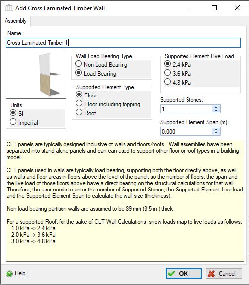
This dialog can be used to:
- define and add a "CLT wall" sub-assembly to a "Custom Wall" assembly in the project, or
- modify or view "CLT wall" sub-assembly to a "Custom Wall" assembly in the project.
| Description / Assumptions / Limits | Required inputs |
|---|---|
CLT wall (Load Bearing)
CLT wall (Non Load Bearing)
|
All CLT Walls
CLT Load Bearing Walls
|
Seismic Note:
Since the CLT panels are very rigid elements and resist lateral loads well, their size and mass are not likely to be affected by the seismic loading. There is an increase in support edge connections in high seismicity regions.
Wall Panels:
CLT panels used in walls would typically be load bearing, supporting both the floor directly above, as well as wall and floor areas in floors above the level of the panel. In almost all applications, openings in walls are cut in the factory, and there is no reinforcement placed around openings, except in abnormal large openings. No reinforcement is added to openings in this model.
- wall height
- lateral support of walls
- dead and live loads of supported floors above
- roof snow load (if the wall supports a roof)
- supported span of upper floors and roof
- number of stories above, if the floors are bearing on the wall
Connections:
- Support edge connections that complement the above noted connection with proprietary steel brackets on the topside and underside of the floor panel. We have assumed that these connectors are to be used when significant diaphragm forces are to be transferred to the walls (i.e. in medium to high seismic zones).
- Spline between panels along the floor panel length.
- Other connections such as wall to wall connections, lintels, balcony supports, parapets, etc, are considered to represent a small percentage of the steel connectors.
On-site Waste:
CLT produces very little waste on site. Panels are custom manufactured in the factory specific for each application on each project. Door and window openings are typically made in the factory, although occasionally some openings are made on site should the opening present a risk of panel damage when lifting. On occasion, panels are sold in bulk and cut to length on site, but this is an uncommon practice. Fastener materials are manufactured off site, although we would expect a small amount of fastener waste due to over-supply or damaged fastener material. Overall, we believe a factor of 1% waste should be carried for both the CLT panels and the steel brakets and splines, and 3% for the fasteners (which is the default construction waste factor in the tool for Screws, Nuts and Bolts) to account for the small amount of waste that could be present. Given the small amount of waste, we would expect it would end up in landfill, although on some projects it may be recycled.
Maintenance and Repair:
In the life of a building, there is no typical repair or maintenance items associated with CLT. Envelope materials that are added to the assembly will be replaced per their replacement cycle.
End of Life:
CLT based buildings are new to the market, so no information is available on CLT would typically perform for the life of the building, after which we would expect they would be disposed of at clean fill dump sites or landfills. In some cases, they could be re-used or used as a fuel source for energy production, or potentially ground into mulch and recycled. Given the lack of relevant information, we treat CLT the same as glulam with respect to the type of disposal at end-of-life.
Envelope Considerations:
CLT panels can accept a wide variety of building envelope systems. A wall system would typically employ a membrane, insulation and cladding system, with or without gypsum board on the interior. Interior walls and ceilings can be exposed (with stain or paint) or encapsulated in gypsum board to comply with fire requirements.
Field Descriptions:
- Name:
- Enter a name for this assembly. All assemblies within a project must be uniquely named within each assembly group. Names maybe alphanumeric (e.g., foundation 1).
Units:- Here you can set the units of measure as either "SI" or "Imperial". Changing the default units here affects only the current assembly but will not override the Default Units of Measure nor the Units of Measure settings for open projects or any other assemblies within open projects.
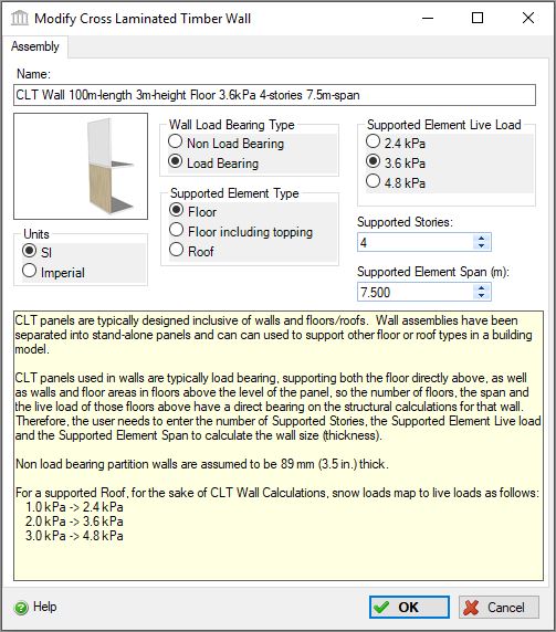
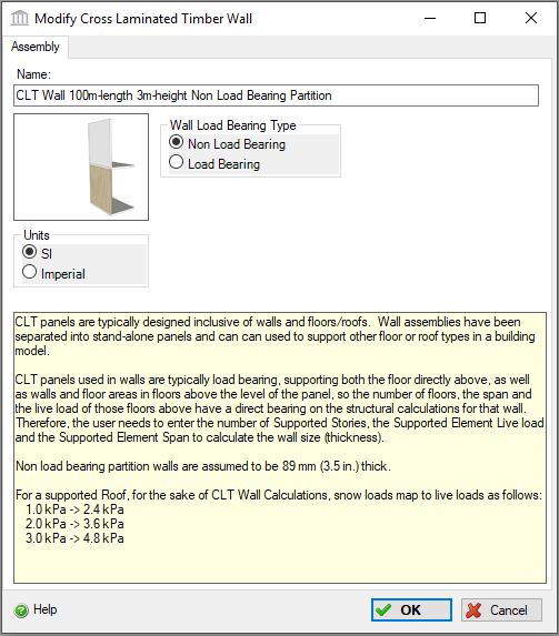
Wall Type:- Here you can choose whether the wall is non load bearing or load bearing.
Click a radio button to select the wall type to be used in this assembly.
- Non Load Bearing
- Load Bearing
Supported Element Type:- For load bearing walls, click a radio button to select the supported element type to be used in this assembly.
- Floor
- Floor including (concrete) topping
- Roof
Supported Element Live Load:- For load bearing walls, click a radio button to select the live load to be carried by this column and beam assembly system.
- 2.4 kPa (50 psf)
- 3.6 kPa (75 psf)
- 4.8 kPa (100 psf)
-
For a supported Roof, for the sake of CLT Wall Calculations, snow loads map to live loads as follows:- 1.0 kPa -> 2.4 kPa
- 2.0 kPa -> 3.6 kPa
- 3.0 kPa -> 4.8 kPa
Supported Stories- For load bearing walls, enter the number of supported stories (for load bearing walls): minimum 1, maximum 10
Supported Element Span- For load bearing walls, enter the average span for elements supported by the wall: maximum of 10 m (32.8 ft)
Help Button:- Click the "Help" button to open the Help pop-up window.
OK Button- Click the "OK" button to accept and save the current assembly settings and close this dialog.
Cancel Button- Click the "Cancel" button to discard the current assembly settings and close this dialog.
Notes:-
- Length:
- The length is inherited from the "Custom Wall" assembly to which this wall "component" sub-assembly belongs.
Height:- The height is inherited from the "Custom Wall" assembly to which this wall "component" sub-assembly belongs.
Openings:- Openings are not captured for this "component" wall assembly. Rather, openings are defined for the "Custom Wall" assembly to which this wall "component" sub-assembly belongs.
Envelope:- Envelope information is not captured for this "component" wall assembly. Rather, openings are defined for the the "Custom Wall" assembly to which this wall "component" sub-assembly belongs.
Duplicate:- This wall "component" sub-assembly can only be duplicated using the "Duplicate" button available in the "Add or Modify Custom Wall" assembly dialog.
Delete:- This wall "component" sub-assembly can only be deleted using the "Delete" button available in the "Add or Modify Custom Wall" assembly dialog.