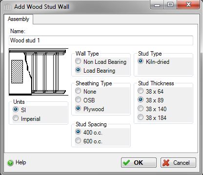
Add or Modify a Wood Stud Wall Assembly
 |
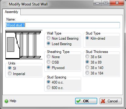 |
This dialog can be used to:
- define and add a "wood stud wall" sub-assembly to a "Custom Wall" assembly in the project, or
- modify or view "wood stud wall" sub-assembly to a "Custom Wall" assembly in the project.
| Description / Assumptions / Limits | Required inputs |
|---|---|
Wood stud wall (Load Bearing)
Wood stud wall (Non Load Bearing)
|
|
Note:
This is one assembly where the user may either specify green or kiln-dried lumber.
Seismic Note:
Seismic adjustments include extra lumber used as compression posts, extra nails, and additional tie down bolts, on load bearing walls only.
Field Descriptions:
- Name:
- Enter a name for this assembly. All assemblies within a project must be uniquely named within each assembly group. Names maybe alphanumeric (e.g., foundation 1).
Units:- Here you can set the units of measure as either "SI" or "Imperial". Changing the default units here affects only the current assembly but will not override the Default Units of Measure nor the Units of Measure settings for open projects or any other assemblies within open projects.
Wall Type:- Here you can whether the wall is non load bearing or load bearing.
Click a radio button to select the wall type to be used in this assembly.
- Non Load Bearing
- Load Bearing
Sheathing Type:- Click a radio button to select the sheathing type to be used in this assembly.
- None
- OSB
- Plywood
Stud Spacing:- Click a radio button to select the stud spacing to be used in this assembly.
- 400 mm o.c. (16 in o.c.)
- 600 mm o.c. (24 in o.c.)
Stud Type:- As of v4.5 (November 2013), Green Lumber is no longer available as a material type, therefore Kiln-Dried Lumber is the only option here. Previous projects that used Green Lumber will automatically be changed to Kiln-Dried when opened in later versions. Kiln-dried lumber has been seasoned (kiln-dried) to moisture content of at least 19%.
- Kiln-Dried Lumber
Stud Thickness:- Click a radio button to select the stud thickness to be used in this assembly.
- 38x64 mm (2x3 in)
- 38x89 mm (2x4 in)
- 38x140 mm (2x6 in)
- 38x184 mm (2x8 in)
Help Button:- Click the "Help" button to open the Help pop-up window.
OK Button- Click the "OK" button to accept and save the current assembly settings and close this dialog.
Cancel Button- Click the "Cancel" button to discard the current assembly settings and close this dialog.
Notes:-
- Length:
- The length is inherited from the "Custom Wall" assembly to which this wall "component" sub-assembly belongs.
Height:- The height is inherited from the "Custom Wall" assembly to which this wall "component" sub-assembly belongs.
Openings:- Openings are not captured for this "component" wall assembly. Rather, openings are defined for the the "Custom Wall" assembly to which this wall "component" sub-assembly belongs.
Envelope:- Envelope information is not captured for this "component" wall assembly. Rather, openings are defined for the the "Custom Wall" assembly to which this wall "component" sub-assembly belongs.
Duplicate:- This wall "component" sub-assembly can only be duplicated using the "Duplicate" button available in the "Add or Modify Custom Wall" assembly dialog.
Delete:- This wall "component" sub-assembly can only be deleted using the "Delete" button available in the "Add or Modify Custom Wall" assembly dialog.