Add or Modify a Steel Stud Wall Assembly
 |
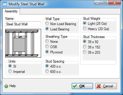 |
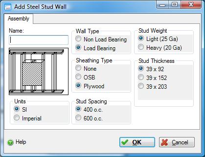
This dialog can be used to:
- define and add a "steel stud wall" sub-assembly to a "Custom Wall" assembly in the project, or
- modify or view "steel stud wall" sub-assembly to a "Custom Wall" assembly in the project.
| Description / Assumptions / Limits | Required inputs |
|---|---|
Steel stud wall (load bearing)
Steel stud wall (non load bearing)
|
|
Seismic Note:
Seismic adjustments include extra galvanized sheet used as cross bracing and gusset plates, in load bearing walls only.
Previous to version 4.1, all "Steel Stud Walls" were assumed to be interior non load bearing walls. All existing "Steel Stud Walls" are automatically assumed to be "Load Bearing" and will be set as such when pre-existing projects are opened in 4.1.10. The only difference between "Load Bearing" and "Non Load Bearing" is that seismic effects are applied to "Load Bearing" walls only. Therefore, only "Steel Stud Walls" in existing Vancouver projects will have their Bills of Materials changed when opened in 4.1.10, or pre-existing projects that are changed to either new location, Los Angeles or Seattle. If you do not wish to have the seismic effects added to existing projects, the user needs to modify each "Steel Stud Wall" assembly by changing the wall type to "Non Load Bearing".
Field Descriptions:
- Name:
- Enter a name for this assembly. All assemblies within a project must be uniquely named within each assembly group. Names maybe alphanumeric (e.g., foundation 1).
Units:- Here you can set the units of measure as either "SI" or "Imperial". Changing the default units here affects only the current assembly but will not override the Default Units of Measure nor the Units of Measure settings for open projects or any other assemblies within open projects.
Wall Type:- Here you can whether the wall is non load bearing or load bearing.
Click a radio button to select the wall type to be used in this assembly.
- Non Load Bearing
- Load Bearing
Sheathing Type:- Click a radio button to select the sheathing type to be used in this assembly.
- None
- OSB
- Plywood
Stud Spacing:- Click a radio button to select the stud spacing to be used in this assembly.
- 400 mm o.c. (16 in o.c.)
- 600 mm o.c. (24 in o.c.)
Stud Weight:- Click a radio button to select the stud weight to be used in this assembly.
- Light (25 Ga)
- Heavy (20 Ga)
Stud Thickness:- Click a radio button to select the stud thickness to be used in this assembly.
- 39x92 mm (2x4 in)
- 39x152 mm (2x6 in)
- 398x203 mm (2x8 in)
Help Button:- Click the "Help" button to open the Help pop-up window.
OK Button- Click the "OK" button to accept and save the current assembly settings and close this dialog.
Cancel Button- Click the "Cancel" button to discard the current assembly settings and close this dialog.
Notes:-
- Length:
- The length is inherited from the "Custom Wall" assembly to which this wall "component" sub-assembly belongs.
Height:- The height is inherited from the "Custom Wall" assembly to which this wall "component" sub-assembly belongs.
Openings:- Openings are not captured for this "component" wall assembly. Rather, openings are defined for the the "Custom Wall" assembly to which this wall "component" sub-assembly belongs.
Envelope:- Envelope information is not captured for this "component" wall assembly. Rather, openings are defined for the the "Custom Wall" assembly to which this wall "component" sub-assembly belongs.
Duplicate:- This wall "component" sub-assembly can only be duplicated using the "Duplicate" button available in the "Add or Modify Custom Wall" assembly dialog.
Delete:- This wall "component" sub-assembly can only be deleted using the "Delete" button available in the "Add or Modify Custom Wall" assembly dialog.