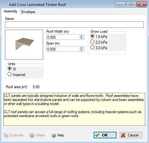
Add or Modify a Cross Laminated Timber Roof
 |
 |
This dialog can be used to:
- define and add a "cross laminated timber roof" assembly to a project, or
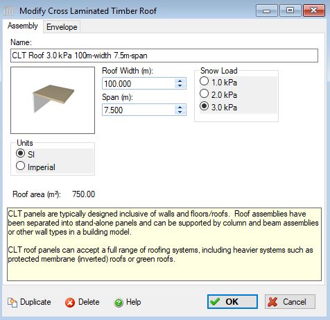
- modify or view "cross laminated timber roof" assembly that has been added to a project.
- define an envelope for this assembly.
| Description / Assumptions / Limits | Required inputs |
|---|---|
Cross Laminated Timber (CLT) roof
|
|
Seismic Note:
Since the CLT panels are very rigid elements and resist lateral loads well, their size and mass are not likely to be affected by the seismic loading. Therefore, there are no seismic adjustments for this assembly.
Connections:
- The roof panel bears directly on the wall and proprietary long screws are fastened through its entire thickness into the wall . Other support edge connections are added to CLT wall assemblies.
On-site Waste:
CLT produces very little waste on site. Panels are custom manufactured in the factory specific for each application on each project. Door and window openings are typically made in the factory, although occasionally some openings are made on site should the opening present a risk of panel damage when lifting. On occasion, panels are sold in bulk and cut to length on site, but this is an uncommon practice. Fastener materials are manufactured off site, although we would expect a small amount of fastener waste due to over-supply or damaged fastener material. Overall, we believe a factor of 1% waste should be carried for CLT roof panels and 3% for the fasteners (which is the default construction waste factor in the tool for Screws, Nuts and Bolts) to account for the small amount of waste that could be present. Given the small amount of waste, we would expect it would end up in landfill, although on some projects it may be recycled.
Maintenance and Repair:
In the life of a building, there is no typical repair or maintenance items associated with CLT. Envelope materials that are added to the assembly will be replaced per their replacement cycle.
End of Life:
CLT based buildings are new to the market, so no information is available on CLT would typically perform for the life of the building, after which we would expect they would be disposed of at clean fill dump sites or landfills. In some cases, they could be re-used or used as a fuel source for energy production, or potentially ground into mulch and recycled. Given the lack of relevant information, treat CLT the same as glulam with respect to the type of disposal at end-of-life.
Envelope Considerations:
CLT panels can accept a wide variety of building envelope systems. CLT roof panels can accept a full range of roofing systems, including heavier systems such as protected membrane (inverted) roofs or green roofs.
Cautionary Note:
- If you want to suspend this assembly on CLT walls, you will need to use the Cross Laminated Timber Wall assembly.
- If you want to suspend this assembly on columns, you will also need to use the Columns and Beams assembly.
Field Descriptions:
- Name:
- Enter a name for this assembly. All assemblies within a project must be uniquely named within each assembly group. Names maybe alphanumeric (e.g., roof 1).
Roof Width:- Enter the roof width in m or ft. The roof width is calculated as follows: Total Roof Area / Supported Span = Roof Width. The user must enter this roof width, in m or ft.
Span:- The span determines the thickness of the roof needed. If a rectangular roof is supported on all four sides, then typically the span would be the short side of that rectangle (within the constraints above)in m or ft. If the floor is supported on two sides, then the span should be the maximum distance between beams (within the constraints above) The user should enter a span and adjust the Roof Width in order to achieve the desired Roof Area.
*For either situation, see Important Note below regarding Span and Width entries.
Snow Load:- Click a radio button to select the live load to be carried by this roof system.
- 1.0 kPa (21 psf)
- 2.0 kPa (42 psf)
- 3.0 kPa (63 psf)
Units:- Here you can set the units of measure as either "SI" or "Imperial". Changing the default units here affects only the current assembly but will not override the Default Units of Measure nor the Units of Measure settings for open projects or any other assemblies within open projects.
Roof Area (m2 or ft2) Note:- As a user friendly check, the total roof area calculated by the application (as per the users input) is reported in the bottom left hand corner of the dialog box.
Duplicate Button- Click the "Duplicate" button to create an exact duplicate of the current assembly. The duplicate assembly will be added to the current project. This button is only available when editing or viewing an assembly that has already been saved in the current project.
Delete Button- Click the "Delete" button to delete the current assembly from the current project. This button is only available when editing or viewing an assembly that has already been saved in the current project.
Help Button:- Click the "Help" button to open the Help pop-up window.
OK Button- Click the "OK" button to accept and save the current assembly settings and close this dialog.
Cancel Button- Click the "Cancel" button to discard the current assembly settings and close this dialog.
Important Note:
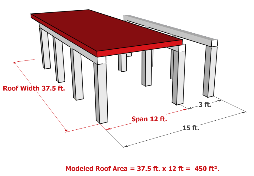
With Roof assemblies, the critical input is the Span. This should be the maximum span that the assembly will be subjected to, and it will determine the size of the assembly needed. For example, in a CLT roof, the span will determine how thick the roof needs to be. The Width is used to account for the total area of the assembly, and may not be the actual width of the assembly. The following Figure 1 shows an actual floor as designed (the yellow floor assembly), and Figure 2 shows how that assembly must be modelled in Impact Estimator (the red equivalent assembly). Notice that the equivalent assembly's width has been changed so the total area of the assembly stays the same, and the span is entered to reflect the maximum span (between the first two rows of beams).
Figure 1
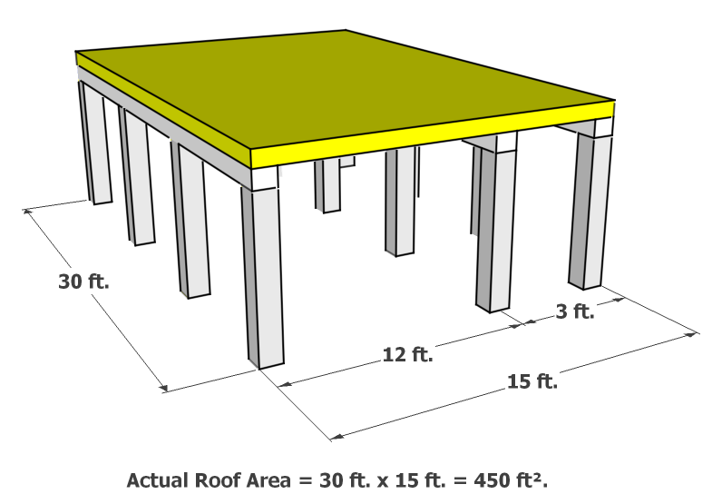
Figure 2