Basic Application Operation
The basic application operation page contains the following sections:
- Add a New Project
- Defining the building/assembly structure
- Defining windows, doors and envelope materials
- Modifying, Copying or Deleting an Assembly
- Generating Results
- Comparing Projects
- Sample Case Studies
Using the Athena Impact Estimator for Buildings
This section describes how the application works from a user’s perspective, with illustrations of some of the screens, dialog boxes and tool bars as well as a discussion of some other application features. If you haven’t already, it is advised that all new users of the application spend a few minutes orienting themselves by quickly running through the tutorial (click here to access the tutorial). You can choose to either just read the following "Using the Athena Impact Estimator for Buildings" passages or follow along by actually duplicating some of the example input screens presented – as we all learn more quickly by doing, we highly recommend the latter.
When you first open the Impact Estimator application, a typical MS Application Program menu bar appears immediately under the Athena - Impact Estimator Tree Control Window title bar (File, Edit, Reports, Tools, Window, Help) along with a set of familiar icons under the menu bar. This first level tool bar is used to initiate project assessments by either creating a new project input file or opening an existing (previously saved) project input file. As with most application programs, you can use the File menu to either create a New project input file or Open a previously saved project input file. You can also click on the first icon (reading left-to-right) to create a new project input file or click on the second icon to open a previously saved project input file. By default, all saved project input files reside in the main Impact Estimator folder unless you select another directory/folder pathway when executing a Save As file operation.
Note: Project files saved with previous versions (3.0.3 or earlier) of the Impact Estimator, can not be opened in version 4.0.
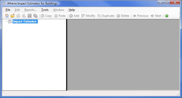
Immediately below the icon tool bar you will see the Impact Estimator Tree Control window which operates as a hierarchical viewer of all inputs entered into the application; allowing you to create and compare projects, insert assemblies, track (review) your design (assembly) inputs and edit (modify) them. Essentially the Impact Estimator Tree Control window allows you to perform the logic operations offered on the main menu bar. For example, within the Impact Estimator Tree Control window you will see the Impact Estimator’s Root Node highlighted (Impact Estimator). With your mouse pointer on the highlighted Root Node "right click" to activate a new vertical menu list (also referred to as the right click menu). From here you can create a New project, Open a previously saved project, Save all active projects, Close all active projects and a number of other operations that will be explained as we move through this section.
This tutorial section will describe the input and output operations using the Impact Estimator Tree Control window as the primary method for navigating through the application. Please note that the software is packaged with a context sensitive HELP file, which provides detailed directions for inputting designs and interpreting results.
Entering a General Project Description
If you are following along at this point with the Impact Estimator open (highly recommended), create a new project input file by right clicking on the highlighted Root Node and click on New Project. An "Add Project " dialog box opens.
Here, you are asked to enter some general information about the project to be modeled (not all of which needs to be entered). You then move around the dialog box using your mouse pointer or tab key, either entering project information or clicking on a number of predefined project descriptors.
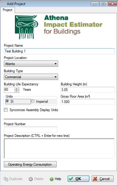
In the example dialog box above, the user has entered the name of the project as "Test Building 1". The user has also provided a more detailed descriptor of the intent of the simulation: "Test Building – wood wall assembly". The location of the project has been specified as "Atlanta" by selecting from the Project Location list menu and scrolling down the menu and clicking on Atlanta.
Both the "Project Name" and "Project Location" are two pieces of information that must be entered because they activate a number of critical functions in the application.
In the "Floor Area" input box a user would typically enter the gross floor area for his design. This value is later used to have the results summarized on a unit floor area basis. Because we are only modeling a single wall assembly in this tutorial example we can accept the floor area input field default value.
In the "Building Height" input box, a user enters the entire height of the building from the lowest sub-grade point to the highest above grade point. This value is later used to calculate construction effects due to using a crane to move some materials. This is a mandator input field.
You then enter the building/assembly life for your project. This invokes typical envelope component maintenance and replacement schedules which is keyed to the building location, type and its life expectancy. You may choose to either select and enter the building life or use the scrolling arrows to change the building life by increments of 20 years. The building life is also used to determine the total life cycle operating energy should you choose to enter the annual operating energy by fuel type.
From the "Building Type" pull-down menu you then select the type of building which best describes your project. As mentioned above, this descriptor is used to invoke the default maintenance and replacement schedule for that building type. "Commercial" is the default building type used for the maintenance and replacement determination should you decide not to select another building type category from the list.
You next select the default units you want the application to use when opening dialog boxes for data input and reporting bill of material quantities. The SI (metric) unit designation is the default unit measure for entering assembly information and has been selected by the user. While the inputs to the application can be specified as either imperial or (SI) metric, the internal application working units are metric and final results are also presented in metric units.
The "Project Number" and "Project Description" are optional input fields for users to further categorize or describe the project.
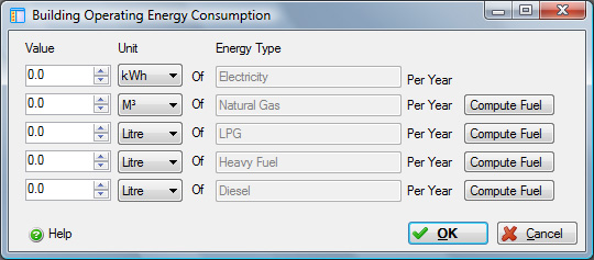
The "Operating Energy Consumption" button opens another window and allows you to input annual operating energy for the building by fuel type (this is another optional input). It is assumed that this operating energy information would come from another simulation tool. The application takes this energy information and converts it to primary energy and calculates related emissions to air, water and land. Later the user may then compare and contrast embodied and operating energy and emissions within and between projects. If your operating energy output is in MJ or BTUs rather than physical units of fuel, simply click on the compute fuel button next to the fuel of interest to have the application convert the fuels energy value into physical units. The application then automatically enters this quantity of fuel in the table (see the "Building Operating Energy Consumption" help file for more detailed instructions on using the compute fuel conversion)
Once the initial project descriptors have been selected, you click on the "OK" button to save the information and exit the dialog box. Click the "Cancel" button to discard the new project. In the Impact Estimator Tree Control window you will now see a plus sign (+) in front of the Root Node. By clicking on the plus sign a Project [P] level object will appear with the title "Test Building 1". You have now successfully created a new project.
Defining the building/assembly structure
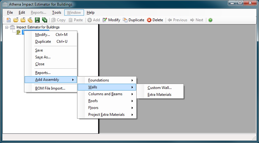
You are now ready to define assemblies. As per our example, we will start with a wall assembly. Simply click on the Project Node to highlight it and then right click to activate the right click menu. Move your mouse pointer down to the "Add Assembly" item on the menu and select "Custom Wall".
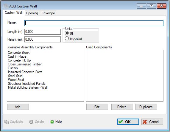
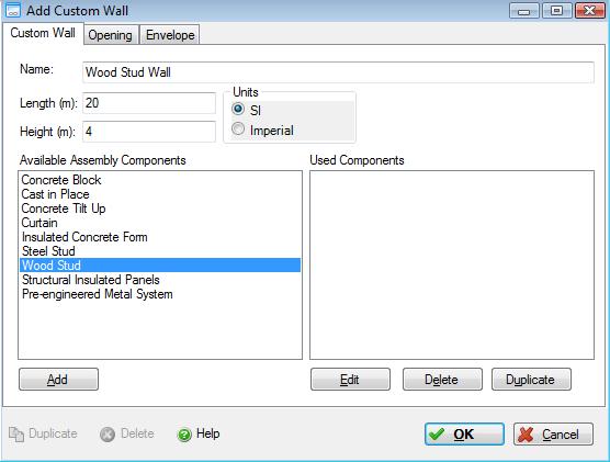
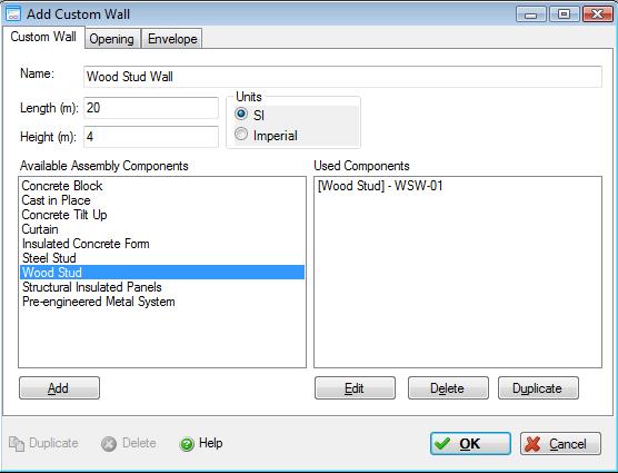
The application then opens the "Add Custom Wall" dialog. Add specific wall components (sub-assemblies) that will make up the desired custom wall assembly. In this dialog, enter the assembly name, i.e., "Wood Stud Wall" and fill in the length and height dimensions. By selecting a wall component then clicking the "Add" button, a wall component specific dialog box will open. In the example below, select the "Wood Stud" wall component and click the "Add" button to open the "Add Wood Stud Wall" dialog.
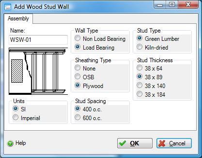
The a "Add Wood Stud Wall" dialog box (see screen capture below) contains a descriptive schematic box with all the input dimensions of interest for the wall. A in the shaded box indicates the total square meters (area) of the openings in the wall; L is the length of the wall in meters; T indicates stud thickness in mm; H is the height of the wall in meters; and S is the spacing between studs. The flashing cursor will automatically be placed in the "Assembly Name" box. Each wall component must be given a unique name, otherwise no data input is possible. After entering an assembly name (e.g., North wall), you can either tab to each of the data input boxes or place the cursor in each box using your mouse.
After entering the wall details and clicking the "OK" button, the wall assembly dialog box will close and a new plus sign [+] will appear beside the Project [P] level object in the Tree Control Window.
If you click on the [+] sign you will cascade to the Assembly Group Node (in the case of our example to the walls group), clicking on the [+] sign beside the Assembly Group takes you to the a list of Assembly Nodes. Double clicking on an Assembly Node will open the "Modify Assembly" dialog. Wall Assemblies, consisting of one or more assembly components (sub-assemblies) is a special Assembly Node and is the only Assembly Node that has a [+] beside it. Clicking on the [+] beside the Wall Assembly Node will display the list of wall components used to define the wall assembly.
Note that in this example SI units have been selected. By clicking on the Imperial button, you can also enter data in Imperial units. Clicking on the Imperial button will also change any entries already made in SI units to show the comparable Imperial unit values. You do not have to maintain the same units throughout the process of selecting and defining assemblies. One assembly can be entered in imperial units and another in SI. As noted earlier, the application automatically converts everything to SI units when making internal calculations.
You can define foundations and additional wall, floor and roof assemblies to complete a three dimensional building space by using the "Add Assembly" menu under the Project [P] level object to access additional structural assembly dialogs. You can also use the Add Assembly menu’s "Extra Basic Materials" category if you want to augment any particular assembly selection or build one up yourself from your own quantity take-off calculations.
Defining windows, doors and envelope materials
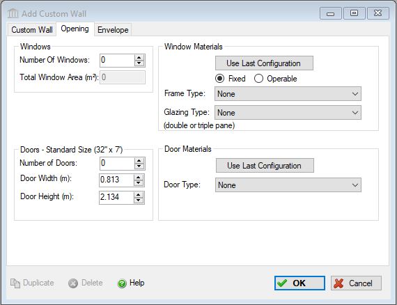
If the "Add Custom Wall" dialog has been closed, in the Tree Control Window right click the new wall assembly to display the assembly object menu and select "Modify" to open the "Modify Custom Wall" dialog. Click on the "Opening" tab to edit the assembly specific opening details. For windows, you can enter the number of window openings, the total window opening area, window frame materials, window glazing type, and whether the windows are fixed or operable. For doors, you can enter the number of door openings and the door type.
One caveat is that you can only define a single window type and/or door type for each assembly object.
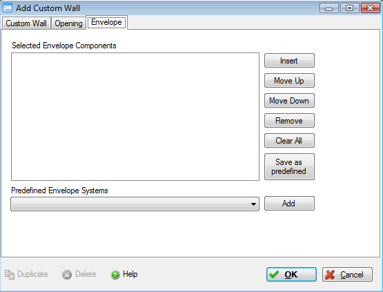
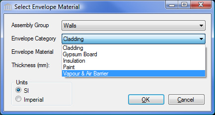
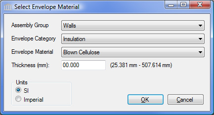
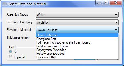
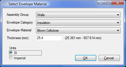
For certain assembly types (i.e., Walls, Floors, Roofs, or Foundations), users can choose to "Define the Envelope" materials (see screen capture below). Essentially, the user now specifies the sandwich make-up of the assembly . Each element of the envelope is defined by selecting the envelope category, envelope material and thickness (where applicable). Once selected the user clicks on the "Add" button to add the specific element to the envelope definition sandwich.
Please remember that when adding envelope materials you are adding individual layers to the sandwich. In the case of a partition wall having painted gypsum board on both sides of the wall, you would therefore need to add gypsum wall board and paint twice.
If the "Add Custom Wall" dialog has been closed, in the Tree Control Window right click the new wall assembly to display the assembly object menu and select "Modify" to open the "Modify Custom Wall" dialog. Click on the "Envelope" tab to edit the assembly specific envelope details. If you have defined one or more envelope systems, select it from the "List of all Predefined Envelope Systems " drop down menu. You can insert new envelope materials and change their ordering in the envelope sandwich. The user can also add an assembly-specific envelope system to the predefined envelope system list by pressing the "Save as Predefined" button.
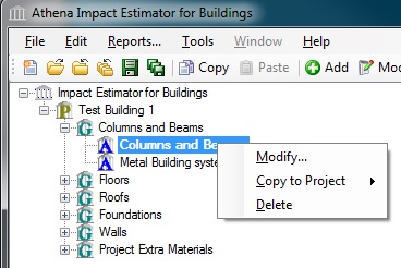
Modifying, Copying or Deleting an Assembly
At the Assembly level of the Tree Control Window, users can modify, copy, or delete a specific assembly (e.g. - the Wood Stud Wall assembly in our example). An assembly can be copied between different open projects or within a single project, this is an easy way to reduce the input chore (see screen capture below).
Generating Results
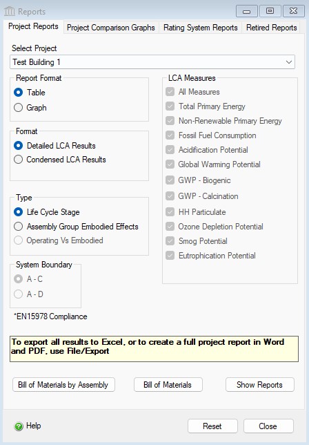
To view either the life cycle inventory results (e.g.- Energy Consumption, Air Emissions, Water Emissions, Land Emissions, and Weighted Resource Use) or the nine aggregated LCA measures (e.g. - Total Primary Energy Consumption , Non-Renewable Energy Consumption Fossil Fuel Consumption, Acidification Potential, Global Warming Potential, Human Health Particulate, Ozone Depletion Potential, Smog Potential, Eutrophication Potential ) as a graph or table you simply do the following:
- Right click one of the Project nodes. (Note: You can also start by selecting the "Reports" menu item from the "Main Menu")
- Select "Reports" from the "Project" menu. The "Reports" dialog will open to the "General" tab.
- Select a Report Format ("Graph" or "Table").
- Select a Format ("Life Cycle Inventory Results" or "LCA Measures").
- Select the Report Type ("By Life Cycle Stages", "Assembly Group Embodied Effects", "Operating Vs Embodied").
- Select the "LCA Measure" effects or "Life Cycle Inventory Results Table" effects.
- Click on the "Bill of Materials" button to generate a BOM report.
- Click on the "Show Reports" button to generate the requested report(s).
Comparing Projects
The Impact Estimator is equipped with a separate utility for comparing the results of two or more project designs across the seven LCA measures. From a reporting perspective, all Impact Estimator results are compiled and accessed at the project level. So if you are interested in comparing two or more assemblies, rather than complete designs, you must input each assembly you want to compare as an individual project. If you are following along with our tutorial example, you currently only have the active "Test Building 1" Project open. To properly use the compare utility you need to have two or more Projects opened. We need to either open additional comparable Projects or enter at least another comparable wall design Project. To continue with the tutorial, open the "Concrete Office Building" and "Steel Office Building" Sample Project files included with this version of the application (you can try entering a second comparable wall design project later).
To open a Project:
- Highlight and right click on the Root Node and click Open from the menu list.
- An Open dialog box will appear listing all the Projects available in the Impact Estimator directory. There should be two Projects listed; one for a "Concrete Office Building" and another for a "Steel Office Building".
- Click on one of the two projects to highlight it and then select Open (double clicking a Project file also opens it). Repeat this procedure to open the second office building Project file.
Two new Projects should now appear in the Impact Estimator Tree Control window. The Impact Estimator always places and displays Projects on the Tree in the same order as which their files were opened or created.
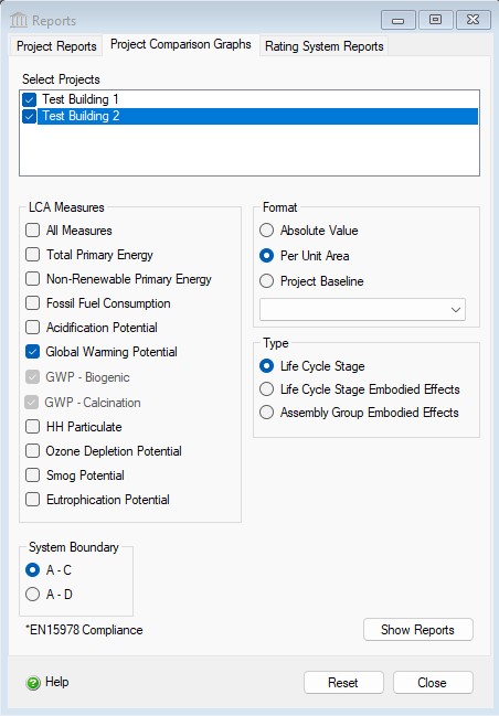
To compare two or more projects, do the following:
- Right click one of the Project nodes. (Note: You can also start by right clicking one of the Project Nodes or by selecting the "Reports" menu item from the "Main Menu" )
- Select "Reports" from the "Root" menu. The "Reports" dialog will open to the "General" tab. Click on the "Comparison Graphs" tab.
- Select two or more projects from the list of open projects.
- Select one or more "LCA Measures" to compare.
- Select the report results "Format" ("Absolute Value", "Per Unit Area", or "Project Baseline"). (If you wish to use one of the selected projects as a baseline, you can pick it from the "Project Baseline" selection list.)
- Select the report "Type" ("Life Cycle Stage", "Assembly Groups").
- Click the "Show Reports" button.
For other Impact Estimator features (e.g., interpreting results, additional TREE capabilities, saving and printing your work, etc.) please refer to the help utility contents, which can be accessed at any time by clicking on the main menu bar "Help".
Sample Case Studies
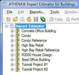
Now that you have successfully specified the structure, envelope, window and door systems for a wall assembly, you are ready to begin entering a new project of your choice or you may choose to open one of our sample case study files and augment it at your discretion. Both the concrete and steel building case studies have only the structure defined at this point, so you can immediately begin to insert envelope materials and window systems. To make it easier for you to check out some of the other reporting capabilities of the application, we have also included the R2000 house file. It is a more complete case study with not only the envelope and windows defined, but it also has the annual operating energy values included as part of the input file.
By now you should be familiar with the basic operations of the Impact Estimator. You are now ready to begin entering a new project of your choice or you may choose to open one of our sample case study files and augment it at your discretion. There are a number of sample case study project files included with the initial installation of the Impact Estimator for Buildings, including at least the following:
- Concrete Office Building
- R2000 House Design
- Steel Office Building
- Condo & Condo Reference
- High Bay Retail & High Bay Retail Reference
- Tutorial Project #1
- Tutorial Project #2
Both the Concrete and Steel Office Building case studies have only the structure defined, so you can immediately begin to insert envelope materials and window systems. To make it easier for you to check out some of the other reporting capabilities of the application, we have also included the R2000 house file. It is a more complete case study with the envelope and windows defined plus it also has the annual operating energy values included.