Basic Application Operation
The basic application operation page contains the following sections:
- Add a New Project
- Defining the roadway/assembly structure
- Modifying, Copying or Deleting an Assembly
- Generating Results
- Comparing Projects
- Sample Case Studies
Using the Athena Pavement LCA
This section describes how the application works from a user’s perspective, with illustrations of some of the screens, dialog boxes and tool bars as well as a discussion of some other application features. If you haven’t already, it is advised that all new users of the application spend a few minutes orienting themselves by quickly running through the tutorial (click here to access the tutorial). You can choose to either just read the following "Using the Athena Pavement LCA" passages or follow along by actually duplicating some of the example input screens presented – as we all learn more quickly by doing, we highly recommend the latter.
When you first open the Pavement LCA application, a typical MS Application Program menu bar appears immediately under the Athena - Pavement LCA Tree Control Window title bar (File, Edit, Reports, Tools, Window, Help) along with a set of familiar icons under the menu bar. This first level tool bar is used to initiate project assessments by either creating a new project input file or opening an existing (previously saved) project input file. As with most application programs, you can use the File menu to either create a New project input file or Open a previously saved project input file. You can also click on the first icon (reading left-to-right) to create a new project input file or click on the second icon to open a previously saved project input file. By default, all saved project input files reside in the main Pavement LCA folder unless you select another directory/folder pathway when executing a Save As file operation.
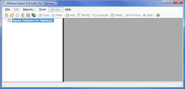
Immediately below the icon tool bar you will see the Pavement LCA Tree Control window which operates as a hierarchical viewer of all inputs entered into the application; allowing you to create and compare projects, insert roadways, track (review) your design (assembly) inputs and edit (modify) them. Essentially the Pavement LCA Tree Control window allows you to perform the logic operations offered on the main menu bar. For example, within the Pavement LCA Tree Control window you will see the Pavement LCA’s Root Node highlighted (Pavement LCA). With your mouse pointer on the highlighted Root Node "right click" to activate a new vertical menu list (also referred to as the right click menu). From here you can create a New project, Open a previously saved project, Save all active projects, Close all active projects and a number of other operations that will be explained as we move through this section.
This tutorial section will describe the input and output operations using the Pavement LCA Tree Control window as the primary method for navigating through the application. Please note that the software is packaged with a context sensitive HELP file, which provides detailed directions for inputting designs and interpreting results.
Entering a General Project Description
If you are following along at this point with the Pavement LCA open (highly recommended), create a new project input file by right clicking on the highlighted Root Node and click on New Project. An "Add Project" dialog box opens.
Here, you are asked to enter some general information about the project to be modeled (not all of which needs to be entered). You then move around the dialog box using your mouse pointer or tab key, either entering project information or clicking on a number of predefined project descriptors.

In the example dialog box above, the user has entered the name of the project as "Highway 1". The user has also provided a more detailed descriptor of the intent of the simulation: "Highway 1 - 2 lane asphalt pavement". The location of the project has been specified as "Central Ontario " by selecting from the Project Location list menu and scrolling down the menu and clicking on "Ontario - Central".
Both the "Project Name" and "Project Location" are two pieces of information that must be entered because they activate a number of critical functions in the application.
In the Paved Surface Area input box a user would typically enter the gross paved surface area for the design. This value is later used to have the results summarized on a unit paved surface area basis. Because we are only modeling a single wall assembly in this tutorial example we can accept the floor area input field default value.
You then enter the Project Lifespan for your project. This will determine the prorated impacts for maintenance or rehabilitation activities whose service life that extend beyond the project lifespan.
You then input the average distances from the site to landfill, and from your shop to the site. This will be used to calculate the transportation effects of disposing of any reclaimed materials and the transportation fo equipment to the site.
You next select the default units you want the application to use when opening dialog boxes for data input and reporting bill of material quantities. The SI (metric) unit designation is the default unit measure for entering assembly information and has been selected by the user. While the inputs to the application can be specified as either imperial or (SI) metric, the internal application working units are metric and final results are also presented in metric units.
The "Project Number" and "Project Description" are optional input fields for users to further categorize or describe the project.
The "Roadway Operating Energy Consumption" tab allows you to input annual roadway operating energy consumption by fuel type (this is another optional input). It is assumed that this operating energy information would come from another simulation tool or be entered to augment the calculated Energy Consumption results. The application takes this energy information and converts it to primary energy and calculates related emissions to air, water and land. Later the user may then compare and contrast embodied and operating energy and emissions within and between projects. If your operating energy output is in MJ or BTUs rather than physical units of fuel, simply click on the compute fuel button next to the fuel of interest to have the application convert the fuels energy value into physical units. The application then automatically enters this quantity of fuel in the table (see the "Roadway Operating Energy Consumption" help file for more detailed instructions on using the compute fuel conversion)

Once the initial project descriptors have been selected, you click on the "OK" button to save the information and exit the dialog box. Click the "Cancel" button to discard the new project. In the Pavement LCA Tree Control window you will now see a plus sign (+) in front of the Root Node. By clicking on the plus sign a Project [P] level object will appear with the title "Highway 1". You have now successfully created a new project.
Defining the roadway/assembly structure
You are now ready to define a roadway. Simply click on the Project Node to highlight it and then right click to activate the right click menu. Move your mouse pointer down to the "Add Assembly" item on the menu and select "Roadway".
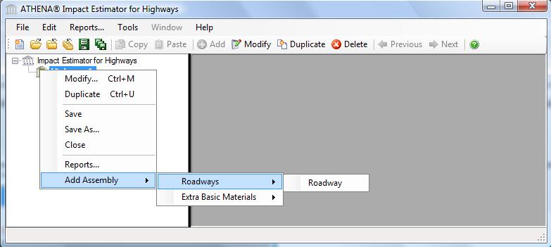
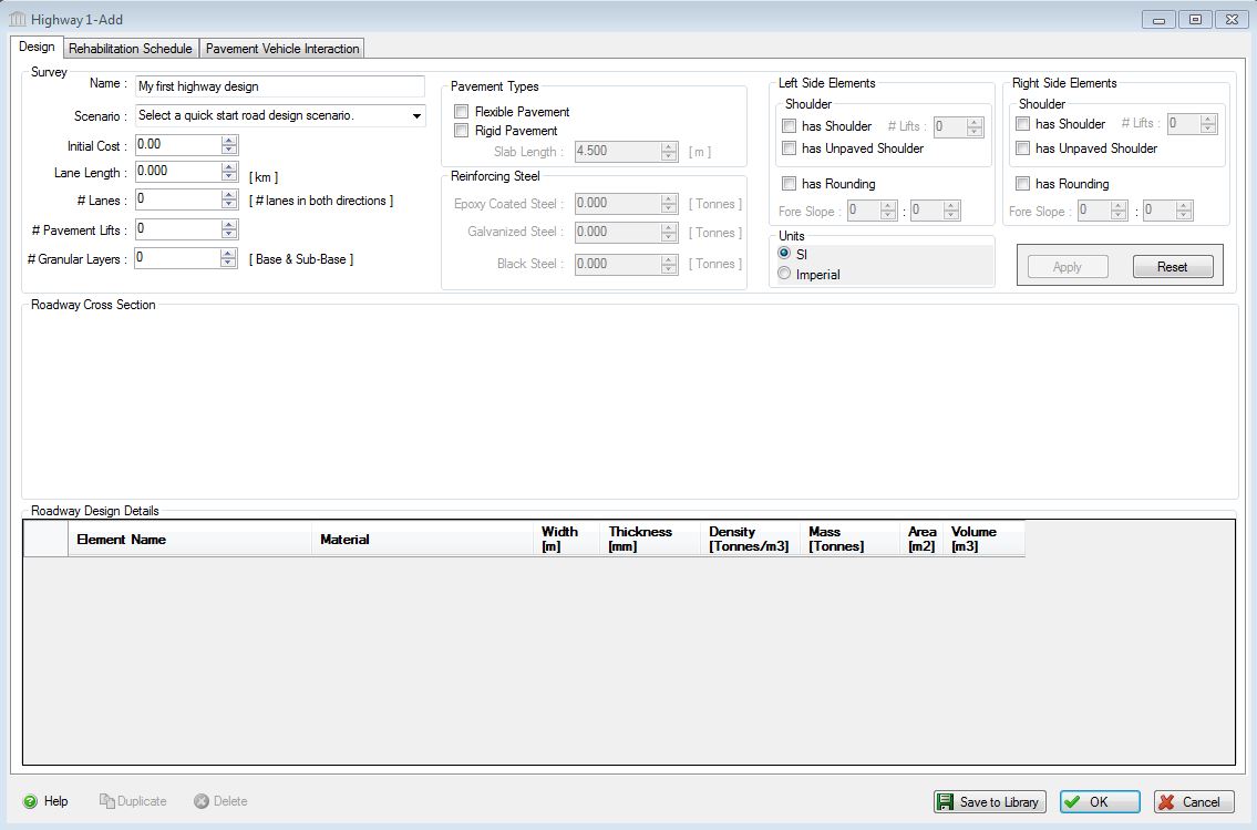
The application then opens the "Add Roadway" dialog. In this dialog, enter the design name, i.e., "Asphalt Highway" and fill in the number of lanes, lane length, number of pavement and granular lifts, chose if the roadway is divided and flexible (asphalt) or rigid (concrete) pavement. Then you can choose if there is a right or left shoulder, the number of pavement lifts of paved shoulders, and if there is an unpaved shoulder. You can also add rounding to the design and specify the ditching fore slope.
Another
way to create a roadway is by clicking on the Scenario drop down list
and selecting a predefined road design from that list, and then
modifying it to suit your design.
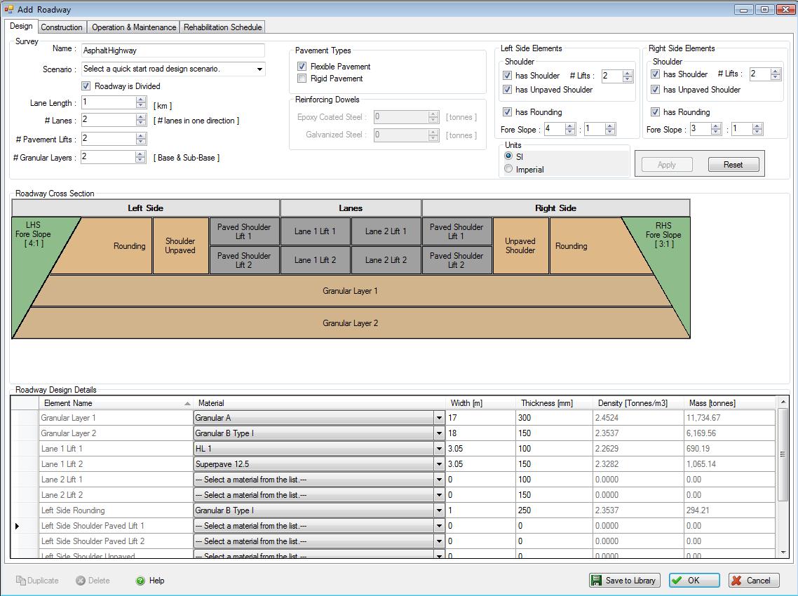
Once you have populated the design details, if you want to be able to use
this design again, click "Save to Library" and it wll be added to the
preset designs in the tool, as well as any other designs you may have
saved. Then click OK, and the Desiign dialog box will close and
Asphalt Highway will appear in the tree as a Roadway assembly in
Project Highway 1.
Modifying, Copying or Deleting an Assembly
At the Assembly level of the Tree Control Window, users can modify, copy, or delete a specific assembly (e.g. - Asphalt Highway in our example). An assembly can be copied between different open projects or within a single project, this is an easy way to reduce the input chore (see screen capture below).

Generating Results
To view either the absolute inventory results (e.g.- Energy Consumption, Air Emissions, Water Emissions, Land Emissions, and Resource Use) or the eight aggregated summary impact measures (e.g. - Fossil Fuel Consumption, Acidification Potential, Global Warming Potential, Human Health Criteria, Ozone Depletion Potential, Smog Potential, Eutrophication Potential) as a graph or table you simply do the following:
- Right click one of the Project nodes. (Note: You can also start by selecting the "Reports" menu item from the "Main Menu")
- Select "Reports" from the "Project" menu. The "Reports" dialog will open to the "General" tab.
- Select a Report Format ("Graph" or "Table").
- Select a Format ("Absolute Values" or "Summary Measures").
- Select the Report Type ("By Life Cycle Stages").
- Select the "Summary Measure" effects or "Absolute Values" effects.
- Click on the "Bill of Materials" button to generate a BOM report.
- Click on the "Show Reports" button to generate the requested report(s).

Comparing Projects
The Pavement LCA is equipped with a separate utility for comparing the results of two or more project designs across the eight summary measures. From a reporting perspective, all Pavement LCA results are compiled and accessed at the project level. So if you are interested in comparing two or more assemblies, rather than complete designs, you must input each assembly you want to compare as an individual project. If you are following along with our tutorial example, you currently only have the active "Highway 1" Project open. To properly use the compare utility you need to have two or more Projects opened. We need to either open additional comparable Projects or enter at least another comparable wall design Project. To continue with the tutorial, create a second comparable highway design project.
Two new Projects should now appear in the Pavement LCA Tree Control window. Pavement LCA always places and displays Projects on the Tree in the same order as which their files were opened or created.
To compare two or more projects, do the following:
- Right click one of the Project nodes. (Note: You can also start by right clicking one of the Project Nodes or by selecting the "Reports" menu item from the "Main Menu" )
- Select "Reports" from the "Root" menu. The "Reports" dialog will open to the "General" tab. Click on the "Comparison Graphs" tab.
- Select two or more projects from the list of open projects.
- Select one or more "Summary Measures" to compare.
- Select the report results "Format" ("Absolute Value", "Per Unit Area", or "Project Baseline"). (If you wish to use one of the selected projects as a baseline, you can pick it from the "Project Baseline" selection list.)
- Select the report "Type" ("Life Cycle Stage", "Assembly Groups").
- Click the "Show Reports" button.

For other Pavement LCA features (e.g., interpreting results, additional TREE capabilities, saving and printing your work, etc.) please refer to the help utility contents, which can be accessed at any time by clicking on the main menu bar "Help".