Add or Modify a Wood Joist and Plywood or OSB Decking Roof System
 |
 |
This dialog can be used to:
- define and add a "wood joist and plywood or OSB decking roof system" assembly to a project, or
- modify or view "wood joist and plywood or OSB decking roof system" assembly that has been added to a project.
- define an envelope for this assembly.
| Description / Assumptions / Limits | Required inputs |
|---|---|
Wood joists & Plywood decking
(Note: 19mm is the typical decking thickness for most applications) |
|
Seismic Note:
Seismic adjustments include extra nails along the decking edges and blocking at each end of the joist.
Field Descriptions:
- Name:
- Enter a name for this assembly. All assemblies within a project must be uniquely named within each assembly group. Names maybe alphanumeric (e.g., roof 1).
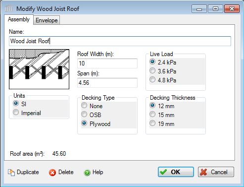
Roof Width:- Enter the roof width in m or ft. The roof width is calculated as follows: Total Roof Area / Supported Span = Roof Width. The user must enter this roof width, in m or ft.
Span:- The Span determines the size of wood joist needed. Enter the maximum span (within the constraints above) of your assembly, in m or ft. i.e.: If an assembly consists of three rows of repeating 5.0 m spans, the user should enter a span 5.0 m and adjust the Roof Width in order to achieve the desired Roof Area.
*See Important Note below regarding Span and Width entries.
Decking Type:- Click a radio button to select either none, plywood or OSB decking materials.
- None
- Plywood
- OSB
Decking Thickness:- Click a radio button to select a decking thickness for the assembly in mm or inches.
- 12 mm (1/2 in.)
- 15 mm (5/8 in.)
- 19 mm (3/4 in.)
Live Load:- Click a radio button to select the live load to be carried by this column and beam assembly system.
- 2.4 kPa (50 psf) represents a typical roof load for a typical office / residential occupancy
- 3.6 kPa (75 psf) represents a typical mechanical/service room loading
- 4.8 kPa (100 psf) would be indicative of heavier roof loads such as assembly areas, balconies/mezzanines, corridors, lobbies/exit areas and storage areas.
Units:- Here you can set the units of measure as either "SI" or "Imperial". Changing the default units here affects only the current assembly but will not override the Default Units of Measure nor the Units of Measure settings for open projects or any other assemblies within open projects.
Roof Area (m2 or ft2) Note:- As a user friendly check, the total roof area calculated by the application (as per the users input) is reported in the bottom left hand corner of the dialog box.
Duplicate Button- Click the "Duplicate" button to create an exact duplicate of the current assembly. The duplicate assembly will be added to the current project. This button is only available when editing or viewing an assembly that has already been saved in the current project.
Delete Button- Click the "Delete" button to delete the current assembly from the current project. This button is only available when editing or viewing an assembly that has already been saved in the current project.
Help Button:- Click the "Help" button to open the Help pop-up window.
OK Button- Click the "OK" button to accept and save the current assembly settings and close this dialog.
Cancel Button- Click the "Cancel" button to discard the current assembly settings and close this dialog.
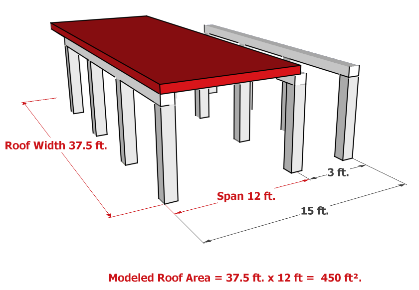
Important Note:
With Roof assemblies, the critical input is the Span. This should be the maximum span that the assembly will be subjected to, and it will determine the size of the assembly needed. For example, in a concrete suspended slab roof, the span will determine how thick the slab needs to be. The Width is used to account for the total area of the assembly, and may not be the actual width of the assembly. The following Figure 1 shows an actual floor as designed (the yellow floor assembly), and Figure 2 shows how that assembly must be modelled in Impact Estimator (the red equivalent assembly). Notice that the equivalent assembly's width has been changed so the total area of the assembly stays the same, and the span is entered to reflect the maximum span (between the first two rows of beams).
Figure 1
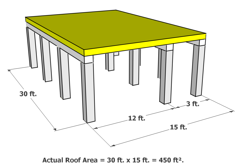
Figure 2