Add or Modify a Steel Joist and Plywood or OSB Flooring System
 |
 |
This dialog can be used to:
- define and add a "steel joist and plywood or OSB flooring system" assembly to a project, or
- modify or view "steel joist and plywood or OSB flooring system" assembly that has been added to a project.
- define an envelope for this assembly.
| Description / Assumptions / Limits | Required inputs |
|---|---|
Steel joists and wood decking system
|
|
Seismic Note:
Seismic adjustments include extra screws along the decking edges and blocking at each end of the joist.
Field Descriptions:
- Name:
- Enter a name for this assembly. All assemblies within a project must be uniquely named within each assembly group. Names maybe alphanumeric (e.g., floor 1).
Floor Width:- Enter the floor width in m or ft.
Span:- Enter the floor span in m or ft.
*See Important Note below regarding Span and Width entries.
Decking Type:- Click a radio button to select either plywood or OSB decking materials.
- None
- OSB
- Plywood
Decking Thickness:- Click a radio button to select a decking thickness for the assembly in mm or inches.
- 12 mm (1/2 in.)
- 15 mm (5/8 in.)
- 19 mm (3/4 in.)
Steel Guage:- Click a radio button to select a steel wire guage for the assembly.
- 16 guage
- 18 guage
Joist Type:- Click a radio button to select a steel joist type for the assembly.
- 39 x 152 mm (1 5/8 x 6 in)
- 39 x 203 mm (1 5/8 x 8 in)
- 39 x 245 mm (1 5/8 x 10 in)
- 39 x 294 mm (1 5/8 x 12 in)
Joist Spacing:- Click a radio button to select a steel joist spacing for the assembly.
- 300 mm (12 in)
- 400 mm (16 in)
- 600 mm (24 in)
Units:- Here you can set the units of measure as either "SI" or "Imperial". Changing the default units here affects only the current assembly but will not override the Default Units of Measure nor the Units of Measure settings for open projects or any other assemblies within open projects.
Floor Area (m2 or ft2) Note:- As a user friendly check, the total floor area calculated by the application (as per the users input) is reported in the bottom left hand corner of the dialog box.
Duplicate Button- Click the "Duplicate" button to create an exact duplicate of the current assembly. The duplicate assembly will be added to the current project. This button is only available when editing or viewing an assembly that has already been saved in the current project.
Delete Button- Click the "Delete" button to delete the current assembly from the current project. This button is only available when editing or viewing an assembly that has already been saved in the current project.
Help Button:- Click the "Help" button to open the Help pop-up window.
OK Button- Click the "OK" button to accept and save the current assembly settings and close this dialog.
Cancel Button- Click the "Cancel" button to discard the current assembly settings and close this dialog.
Important Note:
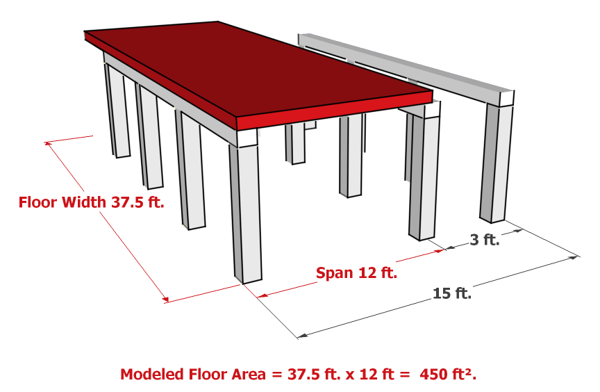
With Floor assemblies, the critical input is the Span. This should be the maximum span that the assembly will be subjected to, and it will determine the size of the assembly needed. For example, in a concrete suspended slab floor, the span will determine how thick the slab needs to be. The Width is used to account for the total area of the assembly, and may not be the actual width of the assembly. The following Figure 1 shows an actual floor as designed (the yellow floor assembly), and Figure 2 shows how that assembly must be modelled in Impact Estimator (the red equivalent assembly). Notice that the equivalent assembly's width has been changed so the total area of the assembly stays the same, and the span is entered to reflect the maximum span (between the first two rows of beams).
Figure 1
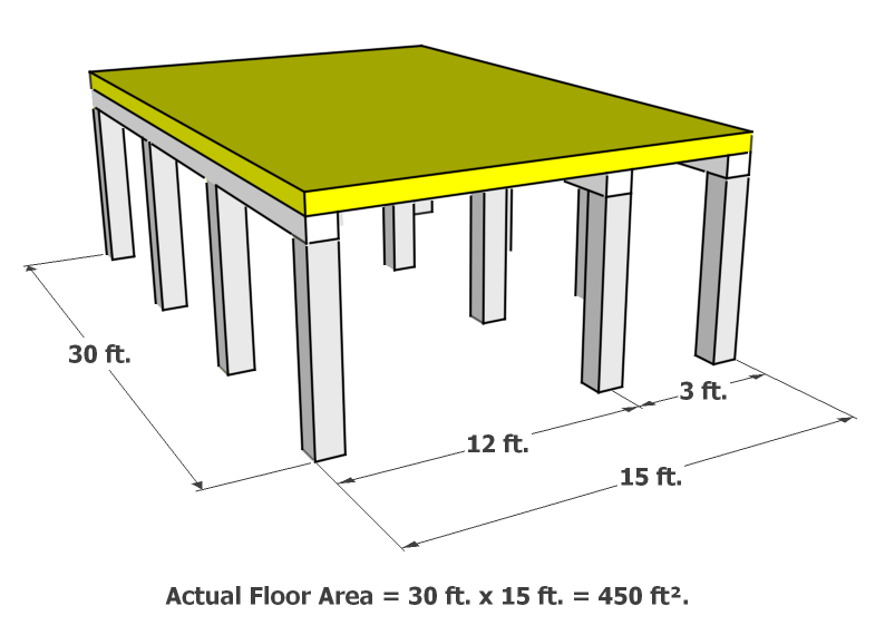
Figure 2